How to Use Orange Pi: Examples, Pinouts, and Specs
Introduction
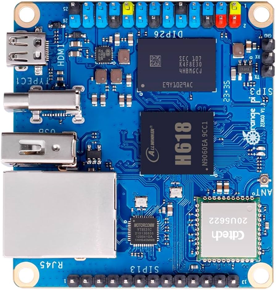
The Orange Pi is a versatile and powerful single-board computer (SBC) designed and manufactured by Shenzhen Xunlong Software. It is a cost-effective alternative to the Raspberry Pi and is widely used in various fields such as Internet of Things (IoT), robotics, embedded systems, and educational projects. The Orange Pi series offers a range of models, each tailored to different use cases and performance requirements.
Explore Projects Built with Orange Pi
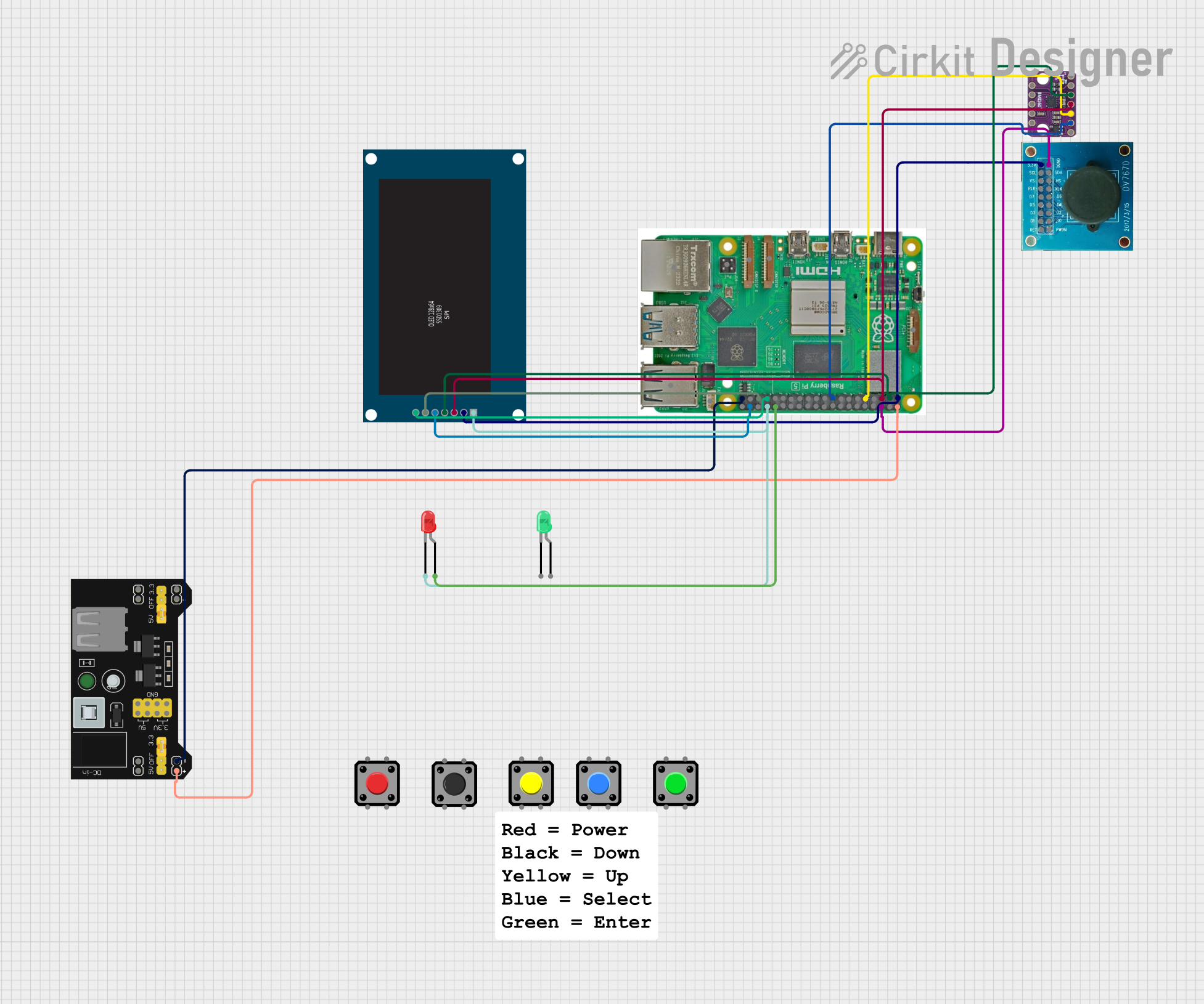
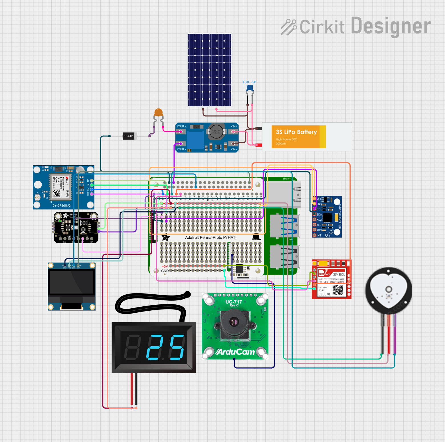


Explore Projects Built with Orange Pi
Technical Specifications
The technical specifications vary across different models of the Orange Pi. Below is a general overview of the specifications you might find in an Orange Pi board. For specific model details, please refer to the manufacturer's datasheet.
General Specifications (Example for Orange Pi Plus 2E)
- CPU: H3 Quad-core Cortex-A7 H.265/HEVC 4K
- GPU: Mali400MP2 GPU @600MHz, Supports OpenGL ES 2.0
- Memory: 2GB DDR3 (shared with GPU)
- Onboard Storage: 16GB eMMC Flash, Micro SD card slot up to 64GB
- Network: 10/100/1000M Ethernet RJ45, WiFi (with antenna), Bluetooth
- Video Input: A CSI input connector allows for the connection of a designed camera module
- Video Outputs: HDMI output with HDCP, HDMI CEC, HDMI 30 function, Integrated CVBS, Supports simultaneous output of HDMI and CVBS
- Audio Output: 3.5 mm Jack and HDMI
- Power Source: DC input, USB OTG input doesn't supply power
- USB Ports: Three USB 2.0 HOST, one USB 2.0 OTG
- Operating System: Android, Ubuntu, Debian, and other Linux distributions
Pin Configuration and Descriptions
| Pin Number | Description | Voltage/Signal |
|---|---|---|
| 1 | 3.3V Power | 3.3V |
| 2 | 5V Power | 5V |
| 3 | TWI SDA | GPIO/I2C Data |
| 4 | 5V Power | 5V |
| 5 | TWI SCL | GPIO/I2C Clock |
| ... | ... | ... |
| GND | Ground | 0V |
Note: The pin configuration table above is a simplified example. For detailed pinout information, please refer to the specific Orange Pi model's datasheet.
Usage Instructions
Setting Up the Orange Pi
- Power Supply: Connect a 5V/2A power supply to the DC input or USB OTG port.
- Operating System: Download the appropriate image for your Orange Pi model from the official website and flash it onto a microSD card.
- Peripherals: Connect a keyboard, mouse, and HDMI display to set up the operating system.
- Network: Connect an Ethernet cable for network access or configure Wi-Fi through the operating system settings.
Best Practices
- Use a reliable power supply to prevent instability.
- Always safely shut down the Orange Pi before disconnecting the power to avoid SD card corruption.
- Keep the board in a case to protect it from static and physical damage.
- Ensure proper cooling to prevent overheating during intensive tasks.
Troubleshooting and FAQs
Common Issues
- Orange Pi doesn't boot: Check the power supply and microSD card image.
- Video output is not working: Verify the HDMI connection and ensure that the display is compatible.
- Network issues: Check the Ethernet cable or Wi-Fi settings.
Solutions and Tips
- Ensure that the microSD card is properly flashed and inserted.
- If using Wi-Fi, confirm that the antenna is attached and the drivers are correctly installed.
- For software-related issues, consult the Orange Pi forums and community resources.
Example Code for Arduino UNO Connectivity
The following is an example of how to blink an LED on pin 13 of an Arduino UNO connected to an Orange Pi via GPIO.
// Define the LED pin
const int ledPin = 13;

// Initialize the LED pin as an output
void setup() {
  pinMode(ledPin, OUTPUT);
}

// Main code to blink the LED
void loop() {
  digitalWrite(ledPin, HIGH);   // Turn the LED on
  delay(1000);                  // Wait for a second
  digitalWrite(ledPin, LOW);    // Turn the LED off
  delay(1000);                  // Wait for a second
}
Note: To run this code, you will need to set up the Arduino IDE on the Orange Pi and configure it to program the Arduino UNO via USB.
For further assistance, refer to the Orange Pi community forums and the official Shenzhen Xunlong Software website for additional resources and support.