How to Use QTR-8A IR Sensor: Examples, Pinouts, and Specs
Introduction
The QTR-8A is an infrared (IR) reflective sensor array that consists of eight IR emitter and detector pairs. It is designed to detect the intensity of reflected IR light, making it ideal for applications such as line-following robots, edge detection, and object tracking. Each sensor in the array outputs an analog voltage proportional to the amount of IR light reflected back to it, enabling precise measurements of distance or object presence.
Explore Projects Built with QTR-8A IR Sensor
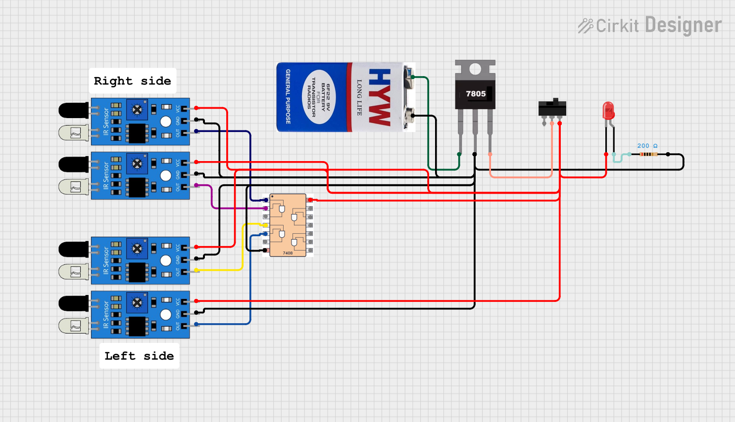
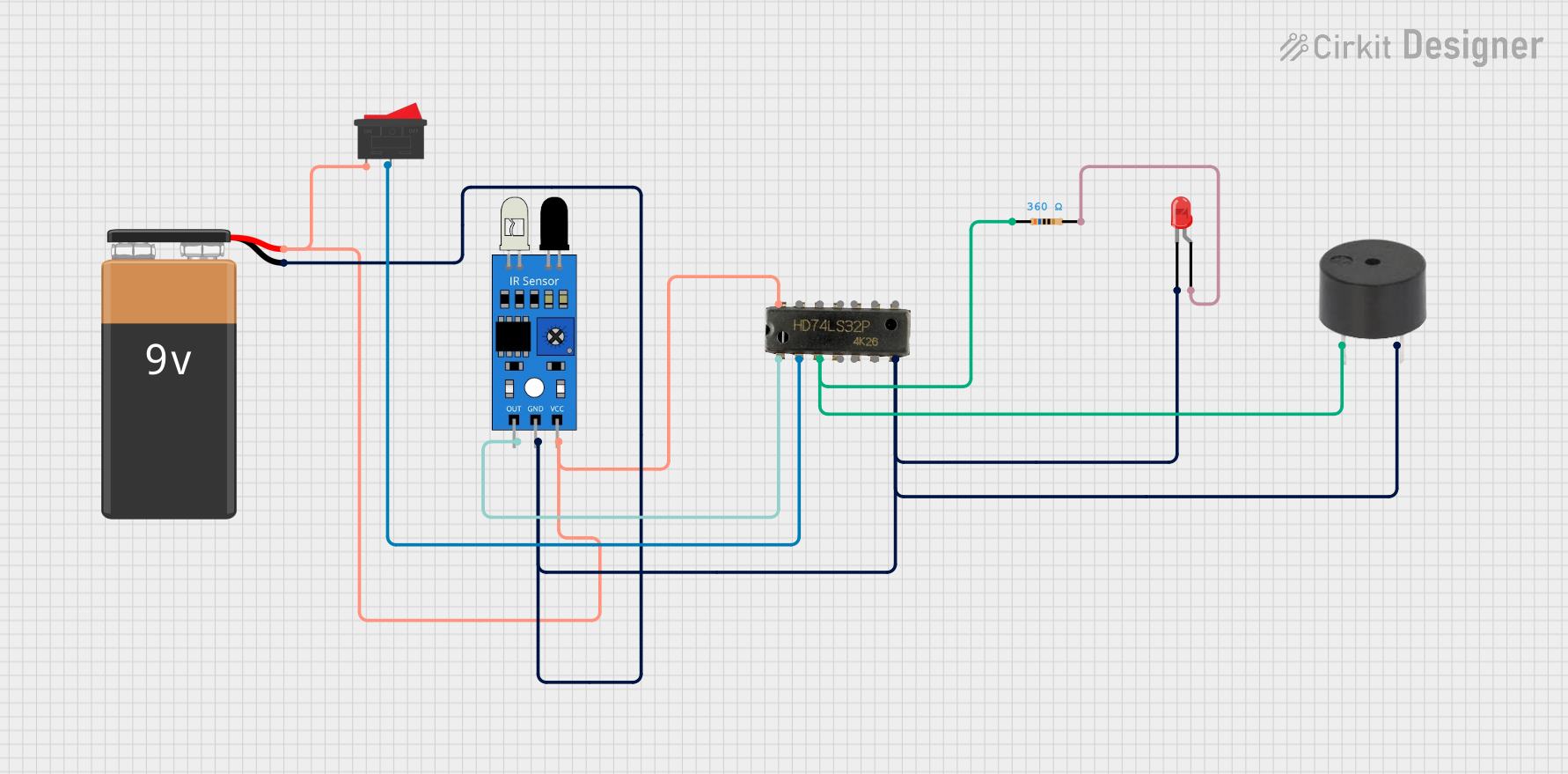
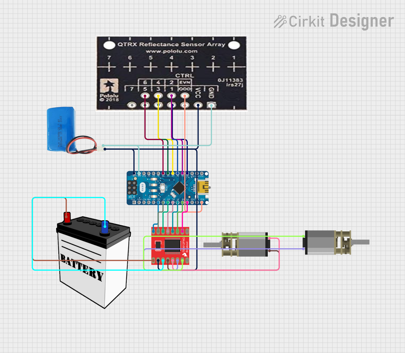

Explore Projects Built with QTR-8A IR Sensor
Common Applications
- Line-following robots
- Edge detection in robotics
- Object detection and tracking
- Proximity sensing
- Industrial automation systems
Technical Specifications
The QTR-8A IR Sensor is a versatile component with the following key specifications:
| Parameter | Value |
|---|---|
| Operating Voltage | 5V DC |
| Operating Current | ~100 mA (with all emitters on) |
| Output Type | Analog voltage (0V to 5V) |
| Number of Sensors | 8 IR emitter-detector pairs |
| Sensor Spacing | 9.525 mm (0.375 inches) |
| Optimal Sensing Distance | 3 mm to 6 mm |
| Dimensions | 76.2 mm × 12.7 mm × 3.2 mm |
| Weight | 3.09 g |
Pin Configuration and Descriptions
The QTR-8A has a 10-pin header for easy interfacing. The pinout is as follows:
| Pin | Name | Description |
|---|---|---|
| 1 | VCC | Power supply input (5V DC). |
| 2 | GND | Ground connection. |
| 3 | OUT1 | Analog output from sensor 1. |
| 4 | OUT2 | Analog output from sensor 2. |
| 5 | OUT3 | Analog output from sensor 3. |
| 6 | OUT4 | Analog output from sensor 4. |
| 7 | OUT5 | Analog output from sensor 5. |
| 8 | OUT6 | Analog output from sensor 6. |
| 9 | OUT7 | Analog output from sensor 7. |
| 10 | OUT8 | Analog output from sensor 8. |
Usage Instructions
How to Use the QTR-8A in a Circuit
- Power the Sensor: Connect the
VCCpin to a 5V DC power source and theGNDpin to ground. - Connect Outputs: Each sensor in the array has a dedicated analog output pin (
OUT1toOUT8). Connect these pins to the analog input pins of a microcontroller (e.g., Arduino UNO). - Read Sensor Values: The analog output voltage from each sensor corresponds to the intensity of reflected IR light. A higher voltage indicates more reflected light, while a lower voltage indicates less reflected light.
Important Considerations
- Optimal Distance: For best results, position the sensor array 3 mm to 6 mm above the surface to be detected.
- Surface Properties: The sensor's performance depends on the reflectivity of the surface. Darker surfaces reflect less IR light, while lighter surfaces reflect more.
- Ambient Light: Minimize ambient IR light interference by using the sensor in controlled lighting conditions or calibrating it for the environment.
- Power Consumption: The sensor array consumes more current when all emitters are active. Ensure your power supply can handle the load.
Example Code for Arduino UNO
The following example demonstrates how to read values from the QTR-8A sensor array using an Arduino UNO:
// QTR-8A IR Sensor Example Code for Arduino UNO
// This code reads analog values from the QTR-8A sensor array and prints them
// to the Serial Monitor.

#define NUM_SENSORS 8 // Number of sensors in the QTR-8A array

// Define the analog input pins connected to the QTR-8A outputs
int sensorPins[NUM_SENSORS] = {A0, A1, A2, A3, A4, A5, A6, A7};

void setup() {
  Serial.begin(9600); // Initialize serial communication at 9600 baud
}

void loop() {
  int sensorValues[NUM_SENSORS]; // Array to store sensor readings

  // Read analog values from each sensor
  for (int i = 0; i < NUM_SENSORS; i++) {
    sensorValues[i] = analogRead(sensorPins[i]);
  }

  // Print sensor values to the Serial Monitor
  for (int i = 0; i < NUM_SENSORS; i++) {
    Serial.print("Sensor ");
    Serial.print(i + 1);
    Serial.print(": ");
    Serial.print(sensorValues[i]);
    Serial.print("\t"); // Tab space for better readability
  }
  Serial.println(); // New line after printing all sensor values

  delay(100); // Delay for 100 ms before the next reading
}
Best Practices
- Calibrate the sensor array for your specific application to improve accuracy.
- Use pull-up resistors on the output pins if required by your microcontroller.
- Avoid exposing the sensor to direct sunlight or strong IR sources, as this may affect performance.
Troubleshooting and FAQs
Common Issues and Solutions
No Output or Incorrect Readings:
- Ensure the sensor is powered correctly (5V to
VCCandGNDconnected). - Verify that the analog output pins are connected to the correct microcontroller pins.
- Check for loose or damaged connections.
- Ensure the sensor is powered correctly (5V to
Inconsistent Readings:
- Ensure the sensor is positioned at the optimal distance (3 mm to 6 mm) from the surface.
- Clean the sensor array to remove dust or debris that may obstruct the IR emitters or detectors.
- Calibrate the sensor for the specific surface and lighting conditions.
High Power Consumption:
- If power consumption is an issue, consider turning off unused emitters by modifying the circuit or using a lower number of active sensors.
FAQs
Q: Can the QTR-8A detect colors?
A: No, the QTR-8A is designed to detect the intensity of reflected IR light, not colors. It is best suited for detecting contrast, such as black and white lines.
Q: Can I use fewer than 8 sensors?
A: Yes, you can use only the sensors you need by connecting the corresponding output pins to your microcontroller and leaving the others unconnected.
Q: How do I calibrate the sensor?
A: Calibration involves reading the sensor values for the lightest and darkest surfaces in your application and mapping the output range accordingly in your code.
Q: Is the QTR-8A compatible with 3.3V systems?
A: The QTR-8A is designed for 5V operation. For 3.3V systems, you may need a level shifter or voltage divider to safely interface the outputs.