How to Use photon 2: Examples, Pinouts, and Specs
Introduction
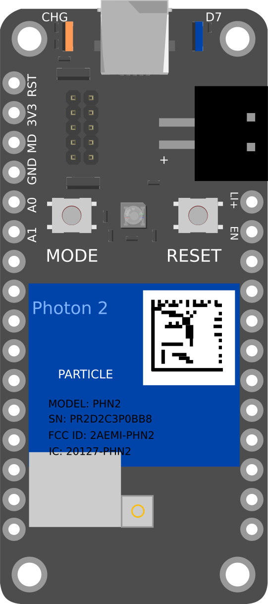
The Photon 2 is a microcontroller development board designed specifically for Internet of Things (IoT) applications. It features built-in Wi-Fi connectivity, a powerful ARM Cortex-M3 processor, and a variety of General-Purpose Input/Output (GPIO) pins for interfacing with sensors and other peripherals. This makes it an ideal choice for developers looking to create connected devices and smart applications.
Explore Projects Built with photon 2
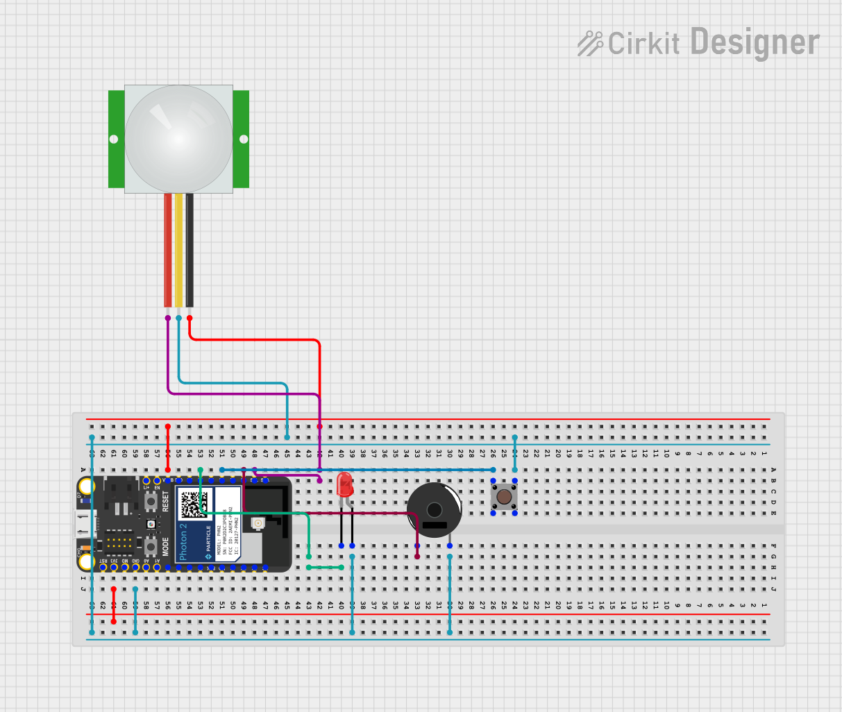
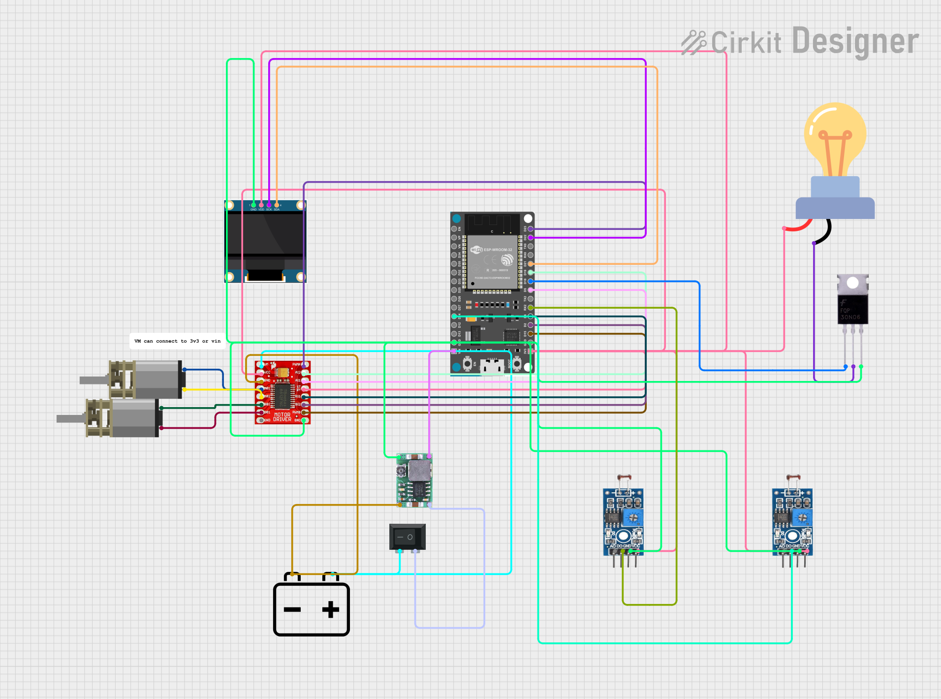

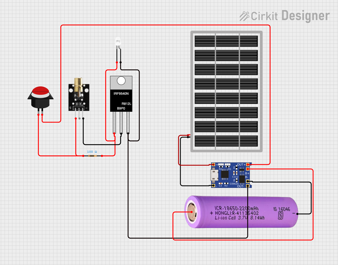
Explore Projects Built with photon 2
Common Applications and Use Cases
- Home Automation: Control and monitor home appliances remotely.
- Environmental Monitoring: Collect and transmit data from sensors measuring temperature, humidity, air quality, etc.
- Wearable Devices: Develop smart wearable gadgets with real-time data transmission.
- Industrial IoT: Monitor and control industrial equipment and processes.
- Smart Agriculture: Automate and monitor agricultural processes like irrigation and soil moisture.
Technical Specifications
Key Technical Details
| Specification | Value |
|---|---|
| Processor | ARM Cortex-M3 |
| Clock Speed | 120 MHz |
| Flash Memory | 1 MB |
| RAM | 256 KB |
| Wi-Fi | 802.11 b/g/n |
| Operating Voltage | 3.3V |
| Input Voltage | 3.6V to 5.5V |
| Digital I/O Pins | 18 |
| Analog Input Pins | 8 |
| PWM Pins | 8 |
| UART | 1 |
| SPI | 1 |
| I2C | 1 |
| USB | Micro USB for power and programming |
| Dimensions | 36mm x 24mm |
Pin Configuration and Descriptions
| Pin Number | Pin Name | Description |
|---|---|---|
| 1 | VIN | Input voltage (3.6V to 5.5V) |
| 2 | GND | Ground |
| 3 | 3V3 | 3.3V output |
| 4 | D0 | Digital I/O |
| 5 | D1 | Digital I/O |
| 6 | D2 | Digital I/O |
| 7 | D3 | Digital I/O |
| 8 | D4 | Digital I/O |
| 9 | D5 | Digital I/O |
| 10 | D6 | Digital I/O |
| 11 | D7 | Digital I/O |
| 12 | A0 | Analog Input |
| 13 | A1 | Analog Input |
| 14 | A2 | Analog Input |
| 15 | A3 | Analog Input |
| 16 | A4 | Analog Input |
| 17 | A5 | Analog Input |
| 18 | A6 | Analog Input |
| 19 | A7 | Analog Input |
| 20 | RX | UART Receive |
| 21 | TX | UART Transmit |
| 22 | SCL | I2C Clock |
| 23 | SDA | I2C Data |
| 24 | SCK | SPI Clock |
| 25 | MISO | SPI Master In Slave Out |
| 26 | MOSI | SPI Master Out Slave In |
| 27 | RST | Reset |
| 28 | USB | Micro USB for power and programming |
Usage Instructions
How to Use the Photon 2 in a Circuit
Powering the Board:
- Connect the VIN pin to a power source (3.6V to 5.5V).
- Alternatively, use the Micro USB port for power and programming.
Connecting to Wi-Fi:
- Use the built-in Wi-Fi module to connect to a network.
- Configure the Wi-Fi settings in your code.
Interfacing with Sensors and Peripherals:
- Use the GPIO pins (D0-D7) for digital input/output.
- Use the analog pins (A0-A7) for reading analog sensors.
- Use the UART, SPI, and I2C interfaces for communication with other devices.
Important Considerations and Best Practices
- Voltage Levels: Ensure that the input voltage does not exceed the specified range (3.6V to 5.5V).
- Pin Usage: Avoid using the same pin for multiple functions simultaneously.
- Wi-Fi Configuration: Secure your Wi-Fi connection with proper authentication and encryption.
- Code Optimization: Optimize your code to make efficient use of the available memory and processing power.
Sample Code for Arduino UNO
#include <WiFi.h>

// Replace with your network credentials
const char* ssid = "your_SSID";
const char* password = "your_PASSWORD";

void setup() {
  // Initialize serial communication
  Serial.begin(115200);

  // Connect to Wi-Fi
  WiFi.begin(ssid, password);

  // Wait for connection
  while (WiFi.status() != WL_CONNECTED) {
    delay(1000);
    Serial.println("Connecting to WiFi...");
  }

  // Print the IP address
  Serial.println("Connected to WiFi");
  Serial.print("IP Address: ");
  Serial.println(WiFi.localIP());
}

void loop() {
  // Your main code here
}
Troubleshooting and FAQs
Common Issues Users Might Face
Wi-Fi Connection Issues:
- Solution: Ensure that the SSID and password are correct. Check the signal strength and try moving closer to the router.
Power Supply Problems:
- Solution: Verify that the input voltage is within the specified range. Use a stable power source.
Pin Conflicts:
- Solution: Double-check the pin configuration in your code and ensure that no pins are being used for multiple functions simultaneously.
Code Upload Failures:
- Solution: Ensure that the correct board and port are selected in the Arduino IDE. Check the USB connection and try a different cable if necessary.
Solutions and Tips for Troubleshooting
- Serial Monitor: Use the Serial Monitor in the Arduino IDE to print debug messages and track the execution of your code.
- LED Indicators: Utilize onboard LEDs to indicate the status of your program (e.g., Wi-Fi connection status).
- Documentation: Refer to the official Photon 2 documentation and community forums for additional support and resources.
By following this documentation, you should be able to effectively utilize the Photon 2 microcontroller development board in your IoT projects. Whether you are a beginner or an experienced developer, the Photon 2 offers a powerful and versatile platform for creating connected devices.