How to Use Closed Loop Stepper Driver: Examples, Pinouts, and Specs
Introduction
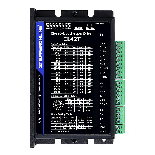
A Closed Loop Stepper Driver is an advanced motor control device designed to enhance the performance of stepper motors. Unlike traditional open-loop stepper drivers, this device uses real-time feedback from the motor to adjust its operation dynamically. This feedback ensures precise positioning, improved efficiency, and reduced issues such as missed steps, motor stalling, and overheating.
Manufactured by Stepper Online, this driver is ideal for applications requiring high accuracy, reliability, and smooth operation. It is commonly used in CNC machines, 3D printers, robotics, and other motion control systems.
Explore Projects Built with Closed Loop Stepper Driver
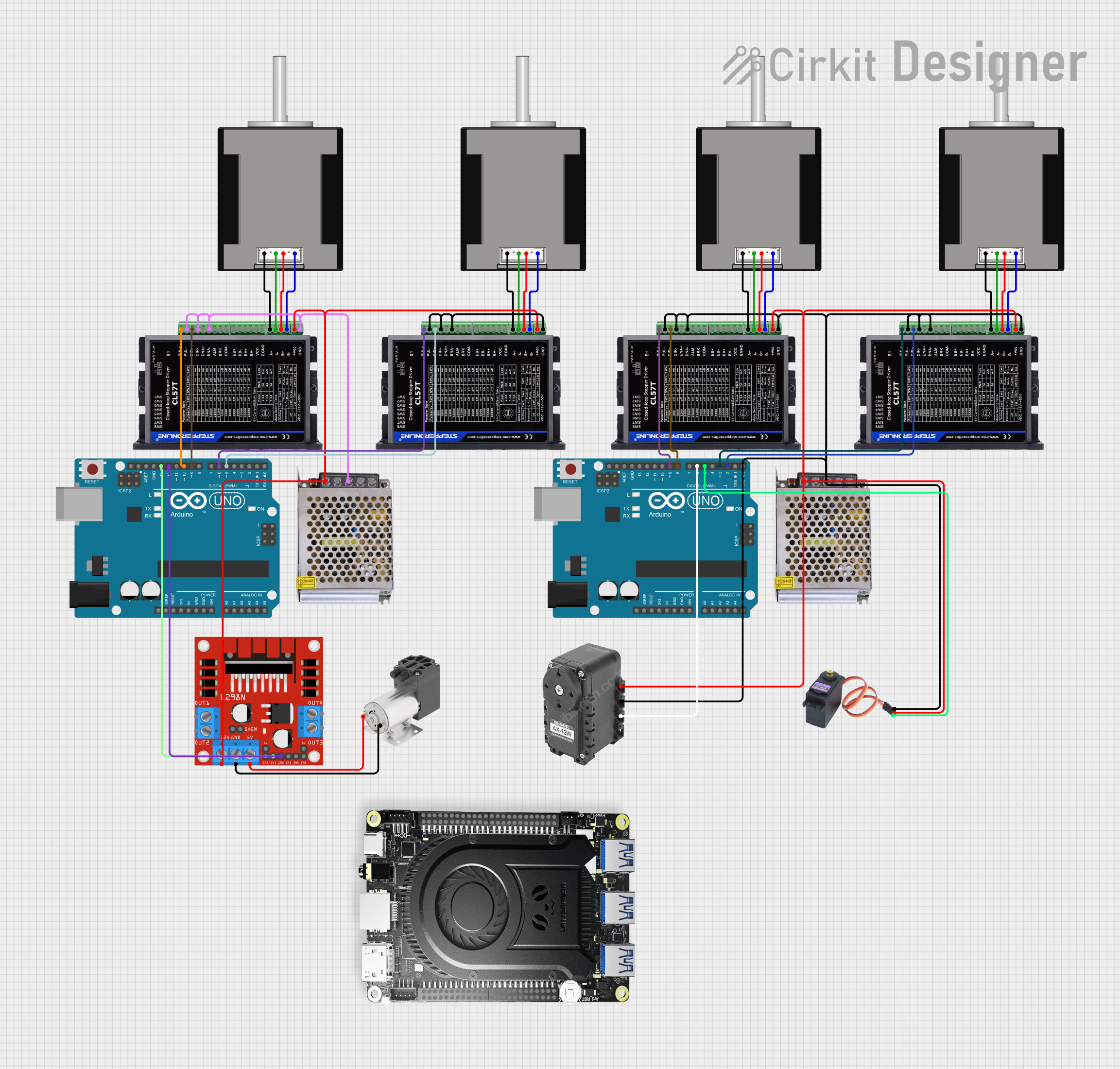

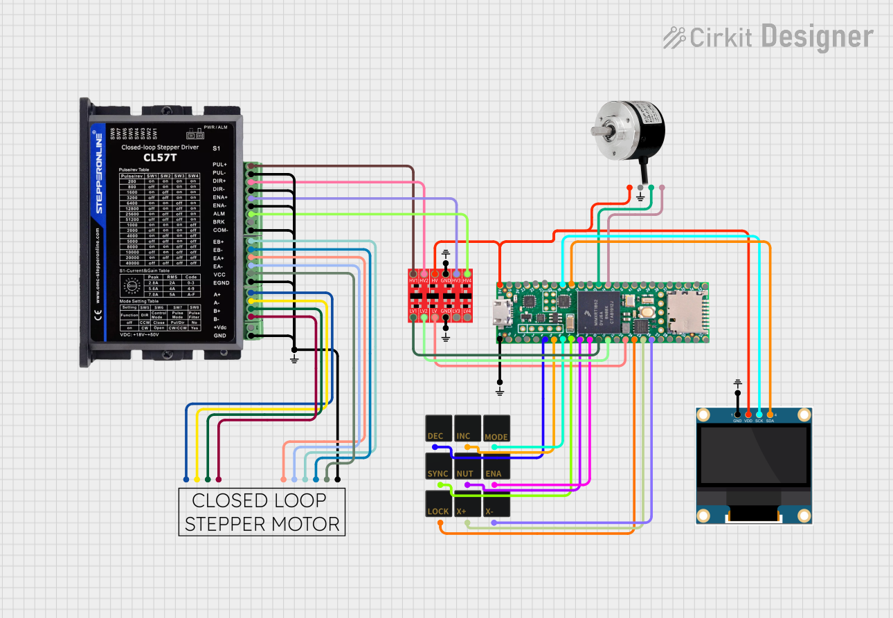
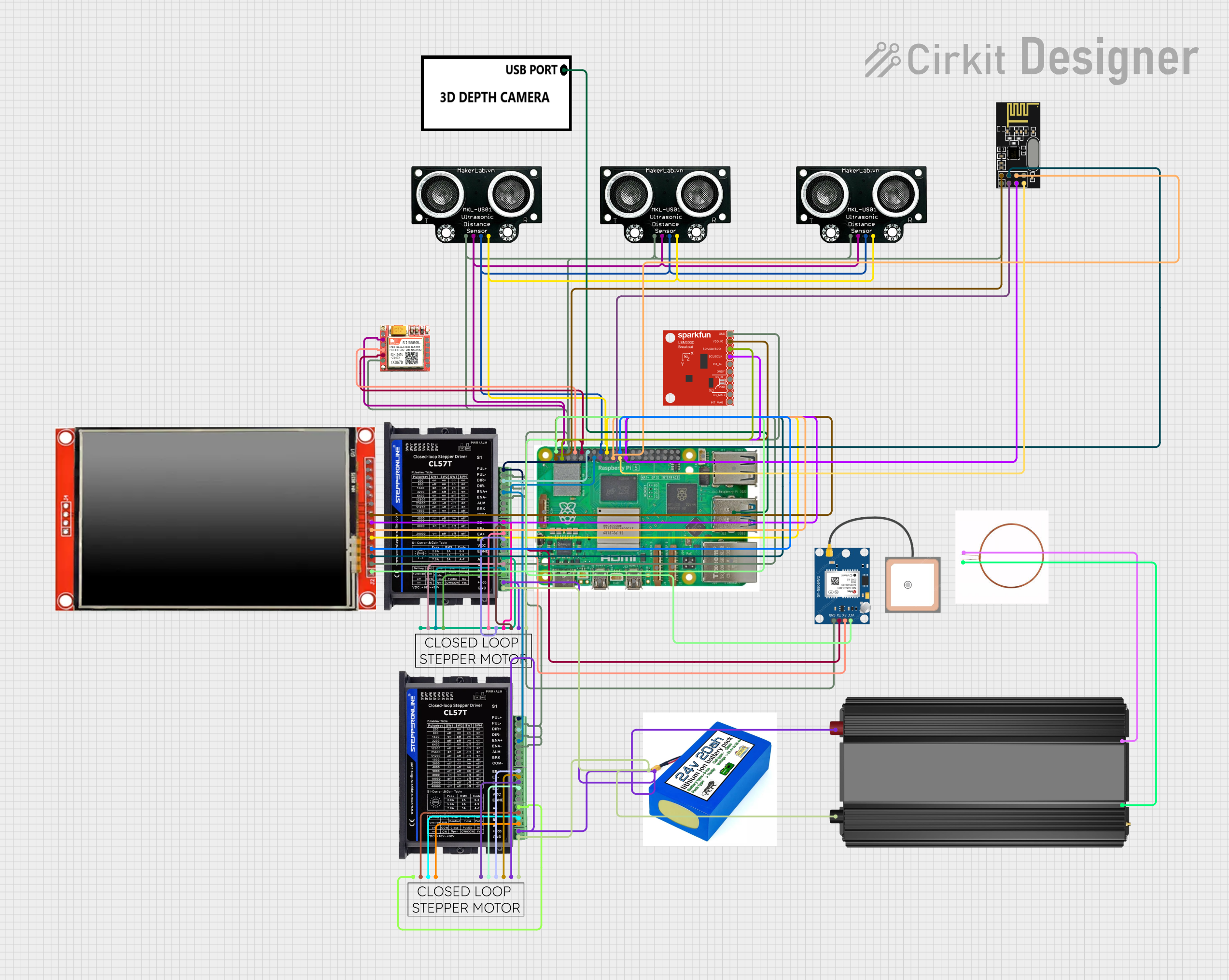
Explore Projects Built with Closed Loop Stepper Driver
Technical Specifications
Below are the key technical details for the Closed Loop Stepper Driver:
| Parameter | Value |
|---|---|
| Input Voltage Range | 20V - 50V DC |
| Output Current | 0.5A - 5.6A (adjustable) |
| Control Signal Type | Pulse/Direction or CW/CCW |
| Microstepping Resolution | Up to 256 microsteps per full step |
| Feedback Type | Encoder-based (closed-loop control) |
| Communication Interface | TTL/RS232 (optional, depending on model) |
| Operating Temperature | -10°C to +45°C |
| Dimensions | 118mm x 75mm x 34mm |
Pin Configuration and Descriptions
The Closed Loop Stepper Driver typically features the following pin configuration:
Power and Motor Connections
| Pin Name | Description |
|---|---|
| V+ | Positive DC power input (20V - 50V) |
| GND | Ground connection for power supply |
| A+ | Motor coil A positive terminal |
| A- | Motor coil A negative terminal |
| B+ | Motor coil B positive terminal |
| B- | Motor coil B negative terminal |
Control Signal Connections
| Pin Name | Description |
|---|---|
| PUL+ | Pulse signal input (positive) |
| PUL- | Pulse signal input (negative) |
| DIR+ | Direction signal input (positive) |
| DIR- | Direction signal input (negative) |
| ENA+ | Enable signal input (positive, optional) |
| ENA- | Enable signal input (negative, optional) |
Encoder Feedback Connections
| Pin Name | Description |
|---|---|
| ENC A+ | Encoder channel A positive signal |
| ENC A- | Encoder channel A negative signal |
| ENC B+ | Encoder channel B positive signal |
| ENC B- | Encoder channel B negative signal |
Usage Instructions
How to Use the Closed Loop Stepper Driver in a Circuit
- Power Supply: Connect a DC power supply (20V - 50V) to the
V+andGNDpins. Ensure the power supply can provide sufficient current for the motor and driver. - Motor Connection: Connect the stepper motor's coils to the
A+,A-,B+, andB-terminals. Refer to the motor's datasheet to identify the correct coil pairs. - Control Signals: Connect the
PUL+,PUL-,DIR+, andDIR-pins to the control system (e.g., Arduino, CNC controller). Use a common ground between the driver and the control system. - Encoder Feedback: Connect the encoder wires from the stepper motor to the
ENC A+,ENC A-,ENC B+, andENC B-pins. This enables closed-loop feedback for precise control. - Enable Signal (Optional): If required, connect the
ENA+andENA-pins to enable or disable the driver via an external signal.
Important Considerations and Best Practices
- Current Adjustment: Set the output current on the driver to match the stepper motor's rated current. This prevents overheating and ensures optimal performance.
- Microstepping: Configure the microstepping resolution based on the application's precision requirements. Higher microstepping improves smoothness but may reduce torque.
- Signal Timing: Ensure the pulse and direction signals meet the driver's timing requirements (e.g., minimum pulse width and delay).
- Cooling: Install the driver in a well-ventilated area or use a heatsink if necessary to prevent overheating during prolonged operation.
Example: Connecting to an Arduino UNO
Below is an example of how to control the Closed Loop Stepper Driver using an Arduino UNO:
Wiring Diagram
PUL+to Arduino pin 3DIR+to Arduino pin 4PUL-,DIR-, andENA-to Arduino GNDENA+to Arduino pin 5 (optional)
Arduino Code
// Define control pins
const int pulsePin = 3; // Pin for pulse signal
const int dirPin = 4;   // Pin for direction signal
const int enablePin = 5; // Pin for enable signal (optional)

void setup() {
  // Set pin modes
  pinMode(pulsePin, OUTPUT);
  pinMode(dirPin, OUTPUT);
  pinMode(enablePin, OUTPUT);

  // Enable the driver
  digitalWrite(enablePin, HIGH); // Set HIGH to enable the driver
}

void loop() {
  // Set direction
  digitalWrite(dirPin, HIGH); // HIGH for one direction, LOW for the other

  // Generate pulses to move the motor
  for (int i = 0; i < 200; i++) { // Move 200 steps
    digitalWrite(pulsePin, HIGH);
    delayMicroseconds(500); // Adjust pulse width for speed
    digitalWrite(pulsePin, LOW);
    delayMicroseconds(500);
  }

  delay(1000); // Wait for 1 second before reversing direction

  // Reverse direction
  digitalWrite(dirPin, LOW);

  // Generate pulses to move the motor in the opposite direction
  for (int i = 0; i < 200; i++) {
    digitalWrite(pulsePin, HIGH);
    delayMicroseconds(500);
    digitalWrite(pulsePin, LOW);
    delayMicroseconds(500);
  }

  delay(1000); // Wait for 1 second before repeating
}
Troubleshooting and FAQs
Common Issues and Solutions
Motor Not Moving
- Cause: Incorrect wiring or loose connections.
- Solution: Double-check all connections, especially the motor coils and control signals.
Motor Stalling or Missing Steps
- Cause: Insufficient current or incorrect microstepping settings.
- Solution: Adjust the driver's current setting and verify the microstepping configuration.
Overheating
- Cause: Driver or motor operating beyond rated current or poor ventilation.
- Solution: Reduce the current setting and ensure proper cooling.
No Feedback from Encoder
- Cause: Encoder wires not connected or damaged.
- Solution: Verify the encoder connections and check for continuity.
FAQs
Q: Can I use this driver with any stepper motor?
A: The driver is compatible with most stepper motors, but ensure the motor's voltage and current ratings match the driver's specifications.Q: What happens if the encoder feedback is disconnected?
A: The driver will operate in open-loop mode, which may result in reduced accuracy and missed steps.Q: How do I configure the microstepping resolution?
A: Use the DIP switches or software (if supported) on the driver to set the desired microstepping level.Q: Can I use this driver with a 12V power supply?
A: No, the minimum input voltage is 20V. Using a lower voltage may damage the driver or result in poor performance.