Cirkit Designer Logo
Cirkit Designer
Your all-in-one circuit design IDE
Home / 
Component Documentation

How to Use ESP32-C3-DevKitM-1: Examples, Pinouts, and Specs

Image of ESP32-C3-DevKitM-1
Cirkit Designer LogoDesign with ESP32-C3-DevKitM-1 in Cirkit Designer

Introduction

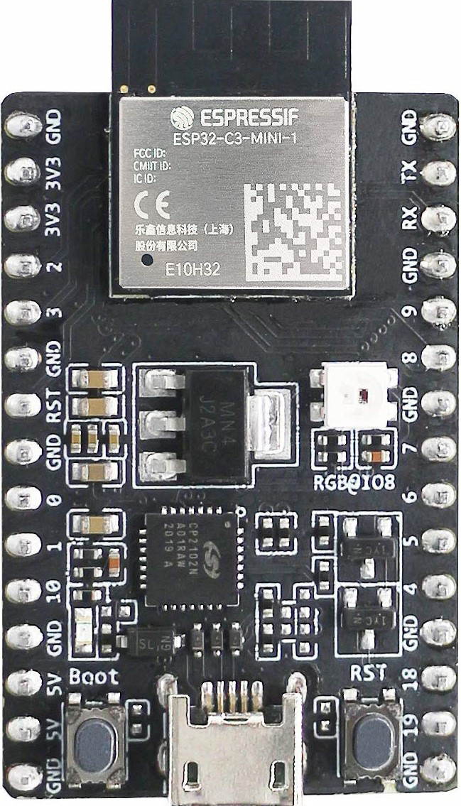
The ESP32-C3-DevKitM-1 is a compact development board based on the ESP32-C3 chip, which integrates Wi-Fi and Bluetooth Low Energy (BLE) capabilities. Designed for Internet of Things (IoT) applications, this board is ideal for prototyping and development due to its small form factor, low power consumption, and robust wireless connectivity. It supports multiple programming environments, including Arduino, ESP-IDF, and MicroPython, making it versatile for developers of all skill levels.

Explore Projects Built with ESP32-C3-DevKitM-1

Use Cirkit Designer to design, explore, and prototype these projects online. Some projects support real-time simulation. Click "Open Project" to start designing instantly!
ESP32-Based Environmental Monitoring and Alert System with Solar Charging
Image of mark: A project utilizing ESP32-C3-DevKitM-1 in a practical application
This circuit features an ESP32 Devkit V1 microcontroller connected to various sensors and modules for monitoring and communication purposes. It includes an MQ-2 gas sensor and a DHT11 temperature and humidity sensor, both interfaced with the ESP32 for environmental data collection. The circuit is powered by a 12V battery, regulated to 5V by step-down converters, and includes a solar charge controller connected to a solar panel for battery charging, a UPS module for power management, and a SIM900A module for GSM communication. Additionally, there is a WS2812 RGB LED strip for visual feedback and a piezo buzzer for audio alerts, both controlled by the ESP32.
Cirkit Designer LogoOpen Project in Cirkit Designer
ESP32 Devkit V1 and OLED Display Bitmap Viewer
Image of Esp32_monochromeimage: A project utilizing ESP32-C3-DevKitM-1 in a practical application
This circuit consists of an ESP32 Devkit V1 microcontroller connected to a 1.3" OLED display via I2C communication. The ESP32 initializes the OLED display and renders a predefined bitmap image on it.
Cirkit Designer LogoOpen Project in Cirkit Designer
ESP32-Based GPS Tracker with SD Card Logging and Barometric Sensor
Image of gps projekt circuit: A project utilizing ESP32-C3-DevKitM-1 in a practical application
This circuit features an ESP32 Wroom Dev Kit as the main microcontroller, interfaced with an MPL3115A2 sensor for pressure and temperature readings, and a Neo 6M GPS module for location tracking. The ESP32 is also connected to an SD card reader for data logging purposes. A voltage regulator is used to step down the USB power supply to 3.3V, which powers the ESP32, the sensor, and the SD card reader.
Cirkit Designer LogoOpen Project in Cirkit Designer
ESP32-Based Environmental Monitoring and Alert System with Solar Charging
Image of Schematic: A project utilizing ESP32-C3-DevKitM-1 in a practical application
This circuit features an ESP32 Devkit V1 microcontroller connected to various sensors and devices, including a DHT11 temperature and humidity sensor, an MQ-2 gas sensor, and a WS2812 RGB LED strip. The ESP32 controls the LED strip and processes sensor readings, while a SIM900A module provides cellular communication capabilities. Power management is handled by a UPS module fed by a 12V battery charged via a solar panel and charge controller, with voltage regulation provided by step-down converters. Additionally, a piezo buzzer is included for audible alerts, and the system's safety is ensured by a circuit breaker connected to a switching power supply for AC to DC conversion.
Cirkit Designer LogoOpen Project in Cirkit Designer

Explore Projects Built with ESP32-C3-DevKitM-1

Use Cirkit Designer to design, explore, and prototype these projects online. Some projects support real-time simulation. Click "Open Project" to start designing instantly!
Image of mark: A project utilizing ESP32-C3-DevKitM-1 in a practical application
ESP32-Based Environmental Monitoring and Alert System with Solar Charging
This circuit features an ESP32 Devkit V1 microcontroller connected to various sensors and modules for monitoring and communication purposes. It includes an MQ-2 gas sensor and a DHT11 temperature and humidity sensor, both interfaced with the ESP32 for environmental data collection. The circuit is powered by a 12V battery, regulated to 5V by step-down converters, and includes a solar charge controller connected to a solar panel for battery charging, a UPS module for power management, and a SIM900A module for GSM communication. Additionally, there is a WS2812 RGB LED strip for visual feedback and a piezo buzzer for audio alerts, both controlled by the ESP32.
Cirkit Designer LogoOpen Project in Cirkit Designer
Image of Esp32_monochromeimage: A project utilizing ESP32-C3-DevKitM-1 in a practical application
ESP32 Devkit V1 and OLED Display Bitmap Viewer
This circuit consists of an ESP32 Devkit V1 microcontroller connected to a 1.3" OLED display via I2C communication. The ESP32 initializes the OLED display and renders a predefined bitmap image on it.
Cirkit Designer LogoOpen Project in Cirkit Designer
Image of gps projekt circuit: A project utilizing ESP32-C3-DevKitM-1 in a practical application
ESP32-Based GPS Tracker with SD Card Logging and Barometric Sensor
This circuit features an ESP32 Wroom Dev Kit as the main microcontroller, interfaced with an MPL3115A2 sensor for pressure and temperature readings, and a Neo 6M GPS module for location tracking. The ESP32 is also connected to an SD card reader for data logging purposes. A voltage regulator is used to step down the USB power supply to 3.3V, which powers the ESP32, the sensor, and the SD card reader.
Cirkit Designer LogoOpen Project in Cirkit Designer
Image of Schematic: A project utilizing ESP32-C3-DevKitM-1 in a practical application
ESP32-Based Environmental Monitoring and Alert System with Solar Charging
This circuit features an ESP32 Devkit V1 microcontroller connected to various sensors and devices, including a DHT11 temperature and humidity sensor, an MQ-2 gas sensor, and a WS2812 RGB LED strip. The ESP32 controls the LED strip and processes sensor readings, while a SIM900A module provides cellular communication capabilities. Power management is handled by a UPS module fed by a 12V battery charged via a solar panel and charge controller, with voltage regulation provided by step-down converters. Additionally, a piezo buzzer is included for audible alerts, and the system's safety is ensured by a circuit breaker connected to a switching power supply for AC to DC conversion.
Cirkit Designer LogoOpen Project in Cirkit Designer

Common Applications and Use Cases

  • IoT devices and smart home automation
  • Wireless sensor networks
  • Wearable devices
  • Industrial automation
  • Prototyping for Wi-Fi and BLE-enabled applications

Technical Specifications

Key Technical Details

Parameter Value
Chipset ESP32-C3 (RISC-V single-core processor)
Wireless Connectivity Wi-Fi 802.11 b/g/n (2.4 GHz), BLE 5.0
Flash Memory 4 MB
Operating Voltage 3.3 V
GPIO Pins 21 (multipurpose, including ADC, PWM, etc.)
Interfaces UART, SPI, I2C, I2S, GPIO, ADC
Power Supply USB 5V or external 3.3V
Dimensions 48.3 mm x 25.4 mm

Pin Configuration and Descriptions

The ESP32-C3-DevKitM-1 features a total of 21 GPIO pins, which can be configured for various functions. Below is the pinout description:

Pin Number Pin Name Functionality
1 GND Ground
2 3V3 3.3V Power Output
3 EN Enable Pin (Active High)
4 IO0 GPIO0, ADC, Boot Mode Selection
5 IO1 GPIO1, ADC, UART TX
6 IO2 GPIO2, ADC, UART RX
7 IO3 GPIO3, ADC
8 IO4 GPIO4, ADC, PWM
9 IO5 GPIO5, ADC, PWM
10 IO6 GPIO6, SPI CLK
11 IO7 GPIO7, SPI MOSI
12 IO8 GPIO8, SPI MISO
13 IO9 GPIO9, I2C SDA
14 IO10 GPIO10, I2C SCL
15 IO11 GPIO11, UART TX
16 IO12 GPIO12, UART RX
17 IO13 GPIO13, PWM
18 IO14 GPIO14, PWM
19 IO15 GPIO15, ADC
20 IO16 GPIO16, ADC
21 IO17 GPIO17, ADC

Usage Instructions

How to Use the ESP32-C3-DevKitM-1 in a Circuit

  1. Powering the Board:

    • Connect the board to a computer or USB power source using a USB-C cable.
    • Alternatively, supply 3.3V to the 3V3 pin and connect GND to ground.
  2. Programming the Board:

    • Install the required drivers for the USB-to-serial interface (if needed).
    • Use a compatible development environment such as Arduino IDE, ESP-IDF, or MicroPython.
    • Select the correct board (e.g., "ESP32C3 Dev Module") and port in your IDE.
  3. Connecting Peripherals:

    • Use the GPIO pins to connect sensors, actuators, or other peripherals.
    • Ensure that the voltage levels of connected devices are compatible with the 3.3V logic of the ESP32-C3.
  4. Uploading Code:

    • Write your code in the chosen IDE and upload it to the board.
    • The board will automatically reset and run the uploaded program.

Important Considerations and Best Practices

  • Voltage Levels: Ensure all connected peripherals operate at 3.3V logic levels to avoid damaging the board.
  • Boot Mode: To enter bootloader mode, hold the IO0 pin low while resetting the board.
  • Power Supply: Use a stable power source to avoid unexpected resets or malfunctions.
  • Antenna Placement: Avoid placing metal objects near the onboard antenna to ensure optimal wireless performance.

Example Code for Arduino IDE

Below is an example of how to blink an LED connected to GPIO4:

// Define the GPIO pin for the LED
#define LED_PIN 4

void setup() {
  // Set the LED pin as an output
  pinMode(LED_PIN, OUTPUT);
}

void loop() {
  // Turn the LED on
  digitalWrite(LED_PIN, HIGH);
  delay(1000); // Wait for 1 second

  // Turn the LED off
  digitalWrite(LED_PIN, LOW);
  delay(1000); // Wait for 1 second
}

Troubleshooting and FAQs

Common Issues and Solutions

  1. The board is not detected by the computer:

    • Ensure the USB cable is functional and supports data transfer.
    • Install the correct USB-to-serial drivers for your operating system.
  2. Code upload fails:

    • Check that the correct board and port are selected in the IDE.
    • Ensure the board is in bootloader mode by holding IO0 low during reset.
  3. Wi-Fi or Bluetooth is not working:

    • Verify that the antenna area is not obstructed.
    • Check your code for proper initialization of Wi-Fi or BLE.
  4. The board resets unexpectedly:

    • Ensure the power supply is stable and capable of providing sufficient current.
    • Avoid short circuits or overloading the GPIO pins.

FAQs

Q: Can I power the board with a 5V supply?
A: Yes, you can power the board via the USB-C port with a 5V supply. However, if using the 3V3 pin, ensure the input voltage is exactly 3.3V.

Q: Does the board support deep sleep mode?
A: Yes, the ESP32-C3 chip supports deep sleep mode for low-power applications.

Q: Can I use the board with MicroPython?
A: Yes, the ESP32-C3-DevKitM-1 is compatible with MicroPython. You can flash the MicroPython firmware and use it for development.

Q: How do I reset the board?
A: Press the reset button on the board to restart it. Alternatively, you can power cycle the board.