
How to Use BAV99: Examples, Pinouts, and Specs
 Design with BAV99 in Cirkit Designer
Introduction
The BAV99, manufactured by Nexperia, is a dual switching diode designed for high-speed switching applications. It features two diodes in a single SOT-23 package, connected in a series configuration. With its low forward voltage drop and fast recovery time, the BAV99 is ideal for use in signal processing, rectification, and other high-frequency applications. Its compact size and reliable performance make it a popular choice in modern electronic designs.
Explore Projects Built with BAV99
 Open Project in Cirkit Designer
 Open Project in Cirkit Designer
 Open Project in Cirkit Designer
 Open Project in Cirkit Designer
Explore Projects Built with BAV99
Open Project in Cirkit DesignerOpen Project in Cirkit DesignerOpen Project in Cirkit DesignerOpen Project in Cirkit DesignerCommon Applications
- High-speed signal switching
- Voltage clamping and protection circuits
- Rectification in low-power applications
- Logic signal level shifting
- RF circuits and mixers
Technical Specifications
Key Electrical Characteristics
| Parameter | Value | Unit |
|---|---|---|
| Maximum Reverse Voltage (VR) | 70 | V |
| Forward Voltage (VF) | 1.25 (at IF = 150 mA) | V |
| Reverse Recovery Time (trr) | 4 | ns |
| Maximum Forward Current (IF) | 215 | mA |
| Power Dissipation (Ptot) | 250 | mW |
| Junction Temperature (Tj) | -55 to +150 | °C |
Pin Configuration and Descriptions
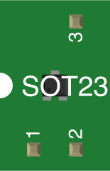
The BAV99 is housed in a 3-pin SOT-23 package. The pinout is as follows:
| Pin Number | Pin Name | Description |
|---|---|---|
| 1 | Anode 1 | Anode of the first diode |
| 2 | Cathode 1 / Anode 2 | Shared cathode of the first diode and anode of the second diode |
| 3 | Cathode 2 | Cathode of the second diode |
Internal Schematic
The internal configuration of the BAV99 consists of two diodes connected in series, as shown below:
Anode 1 (Pin 1) ----|>|---- Cathode 1 / Anode 2 (Pin 2) ----|>|---- Cathode 2 (Pin 3)
Usage Instructions
Using the BAV99 in a Circuit
- Identify the Pins: Refer to the pin configuration table to correctly identify the anodes and cathodes of the diodes.
- Connect in Series or Parallel: Depending on your application, you can use the diodes in series (as they are internally connected) or connect multiple BAV99 components in parallel for higher current handling.
- Voltage Clamping: Use the BAV99 to protect sensitive components by clamping voltage spikes. Connect the diodes across the input and ground to limit voltage to safe levels.
- Signal Switching: The BAV99 is ideal for high-speed signal switching due to its fast recovery time. Ensure the forward current and reverse voltage ratings are not exceeded.
Important Considerations
- Thermal Management: Ensure the total power dissipation does not exceed 250 mW. Use proper heat sinking or PCB design to manage heat.
- Reverse Voltage: Do not exceed the maximum reverse voltage of 70 V to avoid damaging the diodes.
- Forward Current: Limit the forward current to 215 mA to ensure reliable operation.
Example: Using BAV99 with Arduino UNO
The BAV99 can be used for signal rectification or protection in Arduino-based circuits. Below is an example of using the BAV99 for voltage clamping to protect an Arduino input pin:
/*
  Example: Using BAV99 for Voltage Clamping with Arduino UNO
  This circuit protects an Arduino input pin from voltage spikes
  using the BAV99 diode. The diode clamps the voltage to a safe
  level, preventing damage to the microcontroller.

  Circuit:
  - Connect Pin 1 (Anode 1) of BAV99 to the signal source.
  - Connect Pin 2 (Cathode 1 / Anode 2) to GND.
  - Connect Pin 3 (Cathode 2) to the Arduino input pin.
*/

const int inputPin = 2; // Arduino input pin connected to BAV99 Cathode 2

void setup() {
  pinMode(inputPin, INPUT); // Set the pin as input
  Serial.begin(9600);       // Initialize serial communication
}

void loop() {
  int signal = digitalRead(inputPin); // Read the signal
  Serial.println(signal);            // Print the signal value
  delay(100);                        // Small delay for stability
}
Troubleshooting and FAQs
Common Issues
Diode Overheating:
- Cause: Exceeding the maximum forward current or power dissipation.
- Solution: Ensure the current and power ratings are within specified limits. Use proper heat dissipation techniques.
Signal Distortion:
- Cause: High-frequency signals may experience distortion due to improper circuit design.
- Solution: Minimize parasitic capacitance and inductance in the circuit. Use short and direct PCB traces.
Reverse Breakdown:
- Cause: Applying a reverse voltage higher than 70 V.
- Solution: Ensure the reverse voltage is within the specified limit. Use additional protection components if necessary.
FAQs
Q1: Can the BAV99 be used for AC signal rectification?
A1: Yes, the BAV99 can rectify low-power AC signals. However, ensure the voltage and current ratings are not exceeded.
Q2: What is the maximum switching frequency for the BAV99?
A2: The BAV99 is suitable for high-speed applications with a reverse recovery time of 4 ns, making it ideal for frequencies in the MHz range.
Q3: Can I use the BAV99 for voltage level shifting?
A3: Yes, the BAV99 can be used for level shifting in logic circuits. Ensure the voltage levels are within the diode's operating range.
Q4: Is the BAV99 suitable for RF applications?
A4: Yes, the BAV99's fast switching characteristics make it suitable for RF circuits, such as mixers and detectors.