
How to Use ADNS2610: Examples, Pinouts, and Specs
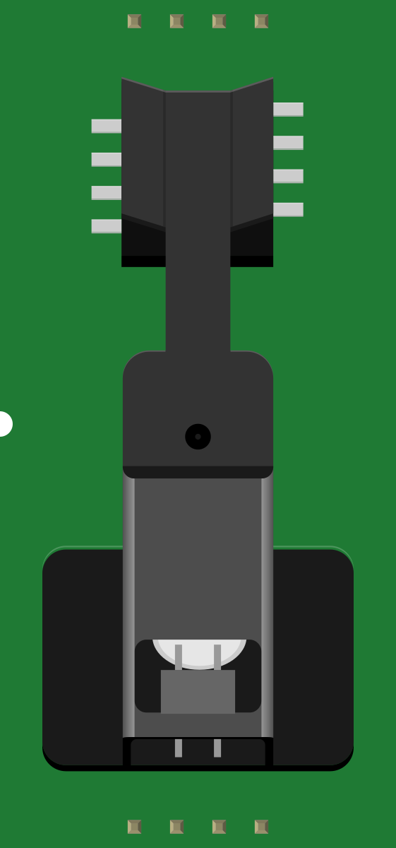
 Design with ADNS2610 in Cirkit Designer
Introduction
The ADNS2610 is a low-power optical mouse sensor designed for use in computer mice. It integrates a CMOS image sensor and a digital signal processor (DSP) to track motion on a wide range of surfaces. This component provides high precision and responsiveness, making it ideal for applications requiring accurate cursor movement. Its compact design and low power consumption make it suitable for battery-operated devices.
Explore Projects Built with ADNS2610
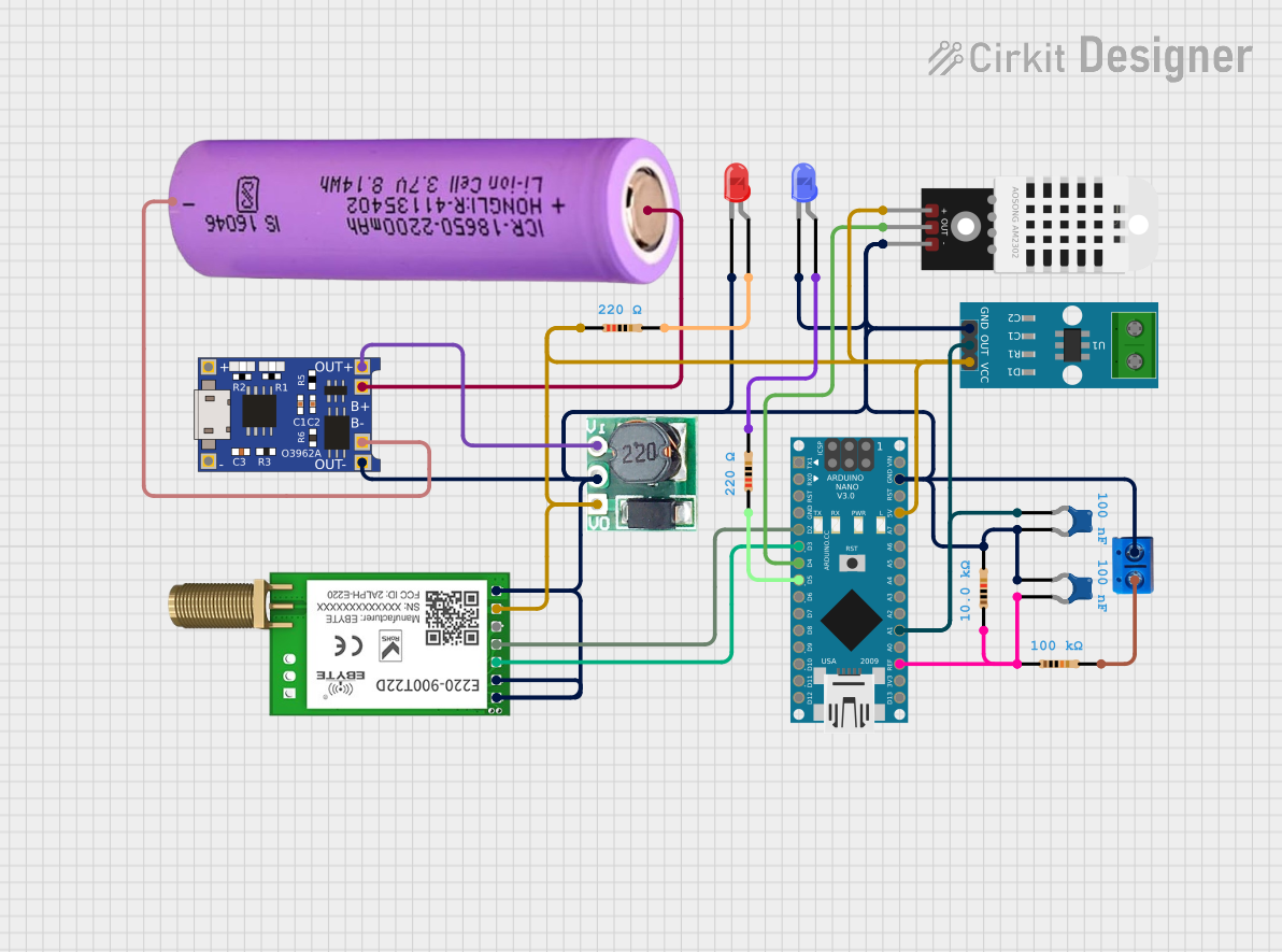 Open Project in Cirkit Designer
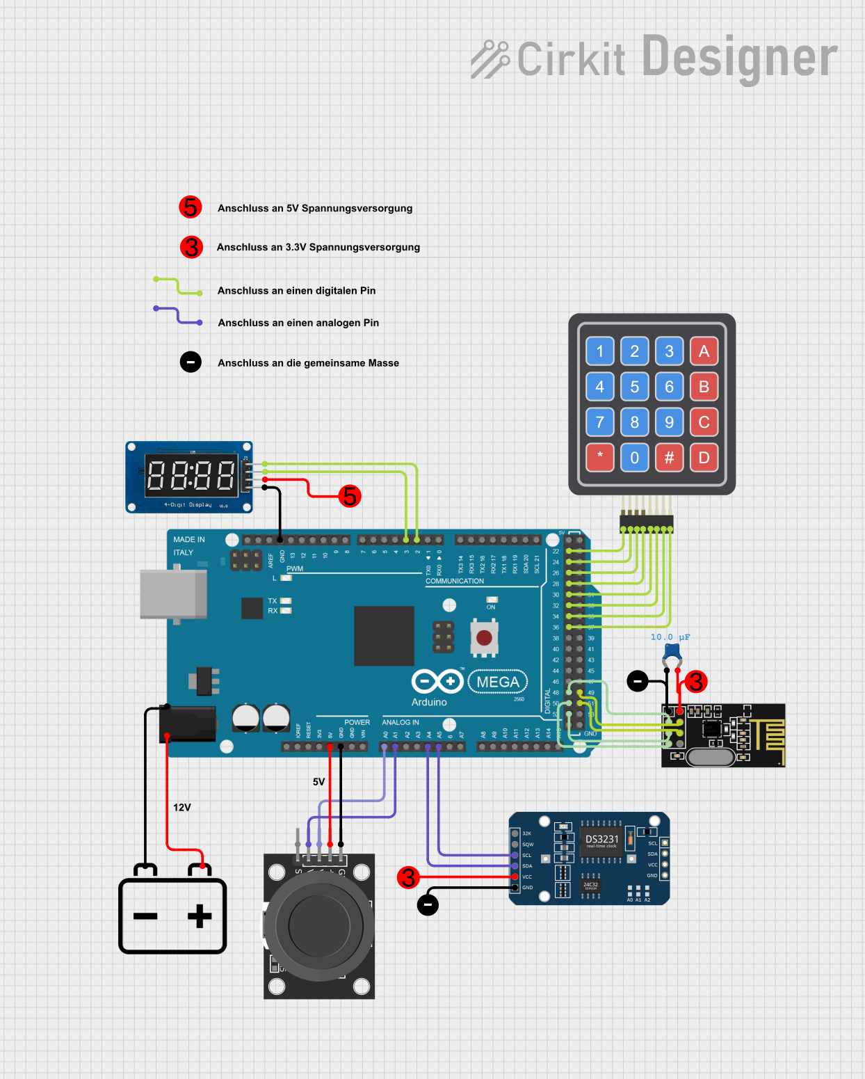 Open Project in Cirkit Designer
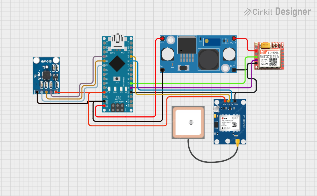 Open Project in Cirkit Designer
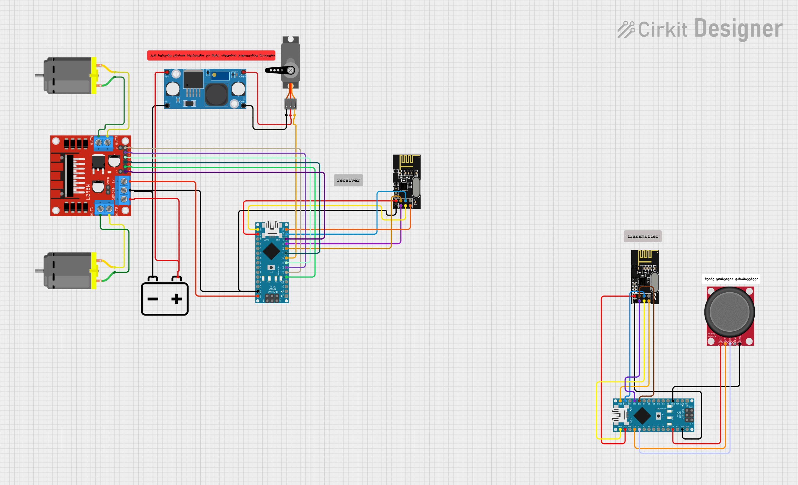 Open Project in Cirkit Designer
Explore Projects Built with ADNS2610
Open Project in Cirkit DesignerOpen Project in Cirkit DesignerOpen Project in Cirkit DesignerOpen Project in Cirkit DesignerCommon Applications and Use Cases
- Optical computer mice
- Motion tracking devices
- Embedded systems requiring surface motion detection
- Educational projects involving optical sensors
Technical Specifications
Key Technical Details
| Parameter | Value |
|---|---|
| Supply Voltage | 4.0 V to 5.5 V |
| Operating Current | 15 mA (typical) |
| Resolution | 400 counts per inch (CPI) |
| Frame Rate | 1500 frames per second (fps) |
| Communication Interface | Serial (SPI-like protocol) |
| Operating Temperature | -20°C to +85°C |
| Package Type | 8-pin staggered dual in-line |
Pin Configuration and Descriptions
| Pin Number | Pin Name | Description |
|---|---|---|
| 1 | VDD | Power supply (4.0 V to 5.5 V) |
| 2 | GND | Ground |
| 3 | SDIO | Serial data input/output for communication |
| 4 | SCLK | Serial clock input |
| 5 | NCS | Chip select (active low) |
| 6 | LED_CTRL | LED control output |
| 7 | OSC_IN | Oscillator input (external clock) |
| 8 | OSC_OUT | Oscillator output |
Usage Instructions
How to Use the ADNS2610 in a Circuit
- Power Supply: Connect the VDD pin to a 4.0 V to 5.5 V power source and the GND pin to ground.
- Communication: Use the SDIO and SCLK pins to communicate with the sensor using a serial protocol. The NCS pin should be pulled low to enable communication.
- LED Control: Connect an LED to the LED_CTRL pin to illuminate the surface for motion tracking. Ensure the LED is properly biased.
- Oscillator: Provide an external clock signal to the OSC_IN pin. The OSC_OUT pin can be used to monitor the clock signal.
Important Considerations and Best Practices
- Surface Compatibility: The ADNS2610 works best on non-glossy, textured surfaces. Avoid transparent or reflective surfaces for optimal performance.
- LED Selection: Use an appropriate LED with a wavelength that matches the sensor's requirements (typically red or infrared).
- Decoupling Capacitors: Place a 0.1 µF decoupling capacitor close to the VDD pin to reduce noise and ensure stable operation.
- Clock Signal: Ensure the external clock signal is stable and within the specified frequency range for proper operation.
Example: Connecting ADNS2610 to Arduino UNO
Below is an example of how to interface the ADNS2610 with an Arduino UNO for basic motion tracking:
// Define pin connections for ADNS2610
#define SDIO_PIN 10  // Serial data input/output pin
#define SCLK_PIN 11  // Serial clock pin
#define NCS_PIN 12   // Chip select pin

void setup() {
  // Initialize serial communication for debugging
  Serial.begin(9600);

  // Configure ADNS2610 pins
  pinMode(SDIO_PIN, OUTPUT);
  pinMode(SCLK_PIN, OUTPUT);
  pinMode(NCS_PIN, OUTPUT);

  // Set initial states
  digitalWrite(NCS_PIN, HIGH);  // Disable chip select
  digitalWrite(SCLK_PIN, LOW);  // Set clock low
}

void loop() {
  // Example: Read motion data from ADNS2610
  digitalWrite(NCS_PIN, LOW);  // Enable chip select

  // Send a read command (example address 0x02 for motion data)
  shiftOut(SDIO_PIN, SCLK_PIN, MSBFIRST, 0x02);

  // Read the motion data
  pinMode(SDIO_PIN, INPUT);  // Set SDIO as input
  byte motionData = shiftIn(SDIO_PIN, SCLK_PIN, MSBFIRST);

  digitalWrite(NCS_PIN, HIGH);  // Disable chip select
  pinMode(SDIO_PIN, OUTPUT);    // Reset SDIO to output

  // Print the motion data to the serial monitor
  Serial.println(motionData);

  delay(100);  // Delay for stability
}
Notes:
- Replace
0x02in the code with the appropriate register address for your application. - Ensure proper pull-up or pull-down resistors are used on the SDIO and SCLK lines if required.
Troubleshooting and FAQs
Common Issues and Solutions
No Motion Detected:
- Ensure the LED is functioning and properly aligned with the sensor.
- Verify the surface is suitable for optical tracking.
Communication Failure:
- Check the connections for SDIO, SCLK, and NCS pins.
- Ensure the Arduino and ADNS2610 share a common ground.
Unstable or Erratic Data:
- Verify the external clock signal is stable and within the specified range.
- Add decoupling capacitors near the power supply pins to reduce noise.
LED Not Turning On:
- Check the LED_CTRL pin output voltage.
- Ensure the LED is correctly biased and not damaged.
FAQs
Q: Can the ADNS2610 work on glossy surfaces?
A: The ADNS2610 performs best on non-glossy, textured surfaces. Glossy or reflective surfaces may cause tracking issues.
Q: What is the maximum frame rate of the ADNS2610?
A: The ADNS2610 supports a maximum frame rate of 1500 frames per second (fps).
Q: Is the ADNS2610 compatible with 3.3 V systems?
A: No, the ADNS2610 requires a supply voltage between 4.0 V and 5.5 V. Use a level shifter if interfacing with a 3.3 V system.
Q: Can I use the ADNS2610 without an external clock?
A: No, the ADNS2610 requires an external clock signal for proper operation.
This concludes the documentation for the ADNS2610.