How to Use dc-dc buck converter: Examples, Pinouts, and Specs
Introduction
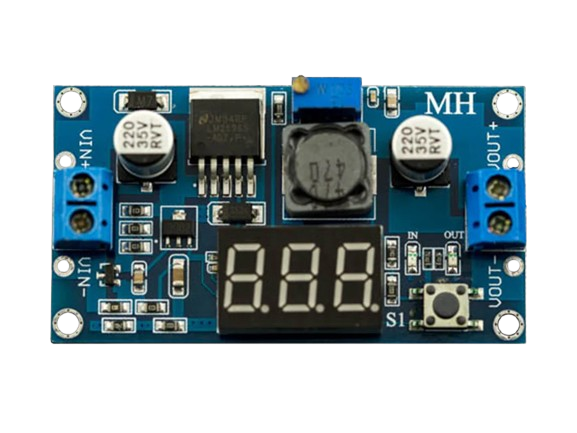
A DC-DC buck converter is a type of power converter designed to step down voltage from a higher level to a lower level while maintaining high efficiency. It achieves this by using a combination of a switching element (such as a transistor), an inductor, a diode, and a capacitor. The buck converter is widely used in applications where efficient power management is critical.
Explore Projects Built with dc-dc buck converter


Explore Projects Built with dc-dc buck converter
Common Applications and Use Cases
- Powering low-voltage devices from higher-voltage sources (e.g., 12V to 5V conversion)
- Battery-powered devices such as smartphones, laptops, and portable electronics
- Voltage regulation in embedded systems and microcontrollers
- Renewable energy systems, such as solar power setups
- Automotive electronics for powering subsystems
Technical Specifications
Below are the general technical specifications for a typical DC-DC buck converter. Note that specific values may vary depending on the model and manufacturer.
Key Technical Details
- Input Voltage Range: 4.5V to 40V (varies by model)
- Output Voltage Range: 1.25V to 37V (adjustable in most models)
- Output Current: Up to 3A (or higher for certain models)
- Efficiency: Up to 95% (depending on load and input/output conditions)
- Switching Frequency: 150 kHz to 1 MHz (varies by design)
- Operating Temperature: -40°C to +85°C (typical)
Pin Configuration and Descriptions
The pinout of a DC-DC buck converter module may vary depending on the design, but a common configuration is as follows:
| Pin Name | Description |
|---|---|
| VIN | Input voltage pin. Connect the higher voltage source to this pin. |
| GND | Ground pin. Connect to the ground of the input and output circuits. |
| VOUT | Output voltage pin. Provides the stepped-down voltage to the load. |
| EN (optional) | Enable pin. Used to turn the converter on or off (active high in most designs). |
| ADJ (optional) | Adjustment pin. Used to set the output voltage (via a potentiometer or resistor). |
Usage Instructions
How to Use the Component in a Circuit
- Connect the Input Voltage:
- Attach the positive terminal of the input voltage source to the
VINpin. - Connect the negative terminal of the input source to the
GNDpin.
- Attach the positive terminal of the input voltage source to the
- Set the Output Voltage:
- If the module has an adjustable output, use the onboard potentiometer or external resistor to set the desired output voltage.
- Measure the output voltage using a multimeter to ensure accuracy.
- Connect the Load:
- Attach the positive terminal of the load to the
VOUTpin. - Connect the negative terminal of the load to the
GNDpin.
- Attach the positive terminal of the load to the
- Enable the Converter (if applicable):
- If the module has an
ENpin, ensure it is connected to a high logic level (e.g., 3.3V or 5V) to enable the converter.
- If the module has an
Important Considerations and Best Practices
- Input Voltage Range: Ensure the input voltage is within the specified range of the module to avoid damage.
- Heat Dissipation: For high-current applications, consider adding a heatsink to the module to prevent overheating.
- Output Filtering: Use additional capacitors at the output if the load is sensitive to voltage ripple.
- Current Limit: Do not exceed the maximum output current rating of the module to avoid damage.
- Polarity: Double-check the polarity of the input and output connections to prevent reverse polarity damage.
Example: Using a Buck Converter with Arduino UNO
Below is an example of how to use a DC-DC buck converter to power an Arduino UNO from a 12V source:
- Connect the 12V source to the
VINandGNDpins of the buck converter. - Adjust the output voltage to 5V using the onboard potentiometer.
- Connect the
VOUTpin of the buck converter to the5Vpin of the Arduino UNO. - Connect the
GNDpin of the buck converter to theGNDpin of the Arduino UNO.
Sample Code for Arduino UNO
// Example code to blink an LED connected to pin 13 of Arduino UNO
// Ensure the Arduino is powered via the buck converter (5V output).

void setup() {
  pinMode(13, OUTPUT); // Set pin 13 as an output pin
}

void loop() {
  digitalWrite(13, HIGH); // Turn the LED on
  delay(1000);            // Wait for 1 second
  digitalWrite(13, LOW);  // Turn the LED off
  delay(1000);            // Wait for 1 second
}
Troubleshooting and FAQs
Common Issues and Solutions
No Output Voltage:
- Check the input voltage to ensure it is within the specified range.
- Verify that the
ENpin is connected to a high logic level (if applicable). - Inspect the connections for loose wires or incorrect polarity.
Output Voltage is Incorrect:
- Adjust the potentiometer or external resistor to set the correct output voltage.
- Measure the input voltage to ensure it is stable and sufficient.
Overheating:
- Ensure the load current does not exceed the module's maximum rating.
- Add a heatsink or improve ventilation around the module.
High Voltage Ripple:
- Add additional filtering capacitors at the output.
- Check the load for sudden current spikes that may cause instability.
FAQs
Q: Can I use a buck converter to power a microcontroller directly?
A: Yes, as long as the output voltage is set to match the microcontroller's operating voltage (e.g., 3.3V or 5V).
Q: What happens if I exceed the input voltage range?
A: Exceeding the input voltage range can damage the module. Always ensure the input voltage is within the specified range.
Q: Can I use a buck converter for AC input?
A: No, a buck converter is designed for DC input only. Use a rectifier and filter circuit to convert AC to DC before using the buck converter.
Q: How do I calculate the efficiency of the buck converter?
A: Efficiency can be calculated using the formula:
[
\text{Efficiency} (%) = \left( \frac{\text{Output Power}}{\text{Input Power}} \right) \times 100
]
Measure the input and output voltages and currents to determine power.
By following this documentation, you can effectively use a DC-DC buck converter in your projects while avoiding common pitfalls.