How to Use Relay Module: Examples, Pinouts, and Specs
Introduction
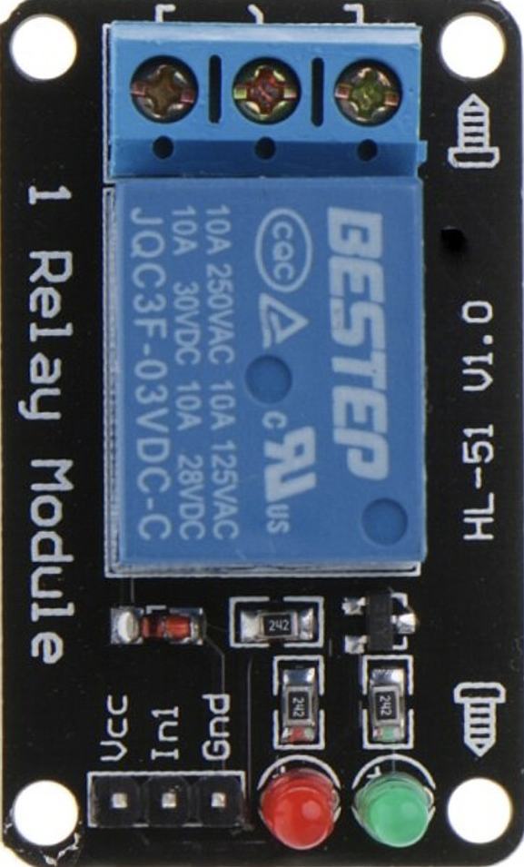
A relay module is an electronic device that allows a low-power signal to control a higher power circuit. It typically consists of one or more relays, which act as electrically operated switches. Relay modules are widely used in automation and control systems to manage devices such as motors, lights, fans, and other electrical equipment. They provide electrical isolation between the control circuit and the high-power circuit, ensuring safety and reliability.
Explore Projects Built with Relay Module


Explore Projects Built with Relay Module
Common Applications and Use Cases
- Home automation systems (e.g., controlling lights or appliances)
- Industrial control systems
- Motor control in robotics
- Smart irrigation systems
- Automotive electronics
- Power management in IoT devices
Technical Specifications
Key Technical Details
- Operating Voltage: 5V DC (common for most relay modules)
- Trigger Voltage: 3.3V to 5V (compatible with microcontrollers like Arduino)
- Relay Type: SPDT (Single Pole Double Throw) or DPDT (Double Pole Double Throw)
- Maximum Load: 10A at 250V AC or 10A at 30V DC (varies by module)
- Isolation: Optocoupler-based isolation for safety
- Indicator: LED to show relay status (ON/OFF)
- Number of Channels: 1, 2, 4, 8, or more (depending on the module)
Pin Configuration and Descriptions
Below is the pin configuration for a typical 1-channel relay module:
| Pin Name | Description |
|---|---|
| VCC | Power supply pin (5V DC) |
| GND | Ground connection |
| IN | Control signal input (connect to microcontroller GPIO pin) |
| COM | Common terminal of the relay switch |
| NO | Normally Open terminal (connected to COM when the relay is activated) |
| NC | Normally Closed terminal (connected to COM when the relay is not activated) |
For multi-channel relay modules, the pin configuration is similar, with additional IN pins for each relay channel (e.g., IN1, IN2, etc.).
Usage Instructions
How to Use the Relay Module in a Circuit
- Power the Module: Connect the
VCCpin to a 5V power source and theGNDpin to ground. - Control Signal: Connect the
INpin to a GPIO pin of a microcontroller (e.g., Arduino). Ensure the control signal voltage matches the relay module's trigger voltage. - Load Connection:
- Connect the device you want to control (e.g., a light bulb) to the
COMandNOterminals if you want the device to turn ON when the relay is activated. - Use the
COMandNCterminals if you want the device to turn OFF when the relay is activated.
- Connect the device you want to control (e.g., a light bulb) to the
- Isolation: Ensure proper electrical isolation between the control circuit and the high-power circuit to avoid damage or hazards.
Important Considerations and Best Practices
- Power Supply: Use a stable 5V power supply to avoid erratic relay behavior.
- Flyback Diode: If controlling inductive loads (e.g., motors), use a flyback diode across the load to protect the relay from voltage spikes.
- Current Ratings: Ensure the load current does not exceed the relay's maximum current rating.
- Optocoupler Isolation: Verify that the module includes optocoupler isolation for added safety.
- Avoid Overheating: Do not operate the relay continuously at its maximum current rating to prevent overheating.
Example Code for Arduino UNO
Below is an example of how to control a relay module using an Arduino UNO:
// Define the pin connected to the relay module's IN pin
const int relayPin = 7;

void setup() {
  // Set the relay pin as an output
  pinMode(relayPin, OUTPUT);

  // Ensure the relay is OFF at startup
  digitalWrite(relayPin, LOW);
}

void loop() {
  // Turn the relay ON
  digitalWrite(relayPin, HIGH);
  delay(5000); // Keep the relay ON for 5 seconds

  // Turn the relay OFF
  digitalWrite(relayPin, LOW);
  delay(5000); // Keep the relay OFF for 5 seconds
}
Note: Replace relayPin with the GPIO pin number you are using to control the relay.
Troubleshooting and FAQs
Common Issues and Solutions
Relay Not Activating:
- Cause: Insufficient control signal voltage.
- Solution: Ensure the control signal voltage matches the relay module's trigger voltage (3.3V or 5V).
Erratic Behavior:
- Cause: Unstable power supply or electrical noise.
- Solution: Use a decoupling capacitor near the relay module's power pins and ensure a stable power source.
Relay Stuck in ON/OFF State:
- Cause: Damaged relay contacts due to overcurrent.
- Solution: Replace the relay module and ensure the load current is within the relay's rated capacity.
LED Indicator Not Working:
- Cause: Faulty LED or insufficient power supply.
- Solution: Check the power connections and replace the module if necessary.
FAQs
Q: Can I use a 3.3V microcontroller with a 5V relay module?
A: Yes, if the relay module supports a 3.3V trigger voltage. Otherwise, use a level shifter or transistor circuit.Q: Can I control AC appliances with a relay module?
A: Yes, ensure the appliance's voltage and current ratings are within the relay's specifications.Q: Why is the relay clicking but not controlling the load?
A: Check the wiring of the load to the relay'sCOM,NO, andNCterminals. Ensure proper connections.Q: Can I use the relay module to control multiple devices?
A: Yes, but only if the total current does not exceed the relay's maximum rating. Use a multi-channel relay module for independent control of multiple devices.