How to Use Polulu DRV 8874: Examples, Pinouts, and Specs
Introduction
The Pololu DRV8874 (Manufacturer Part ID: 4035) is a compact and versatile motor driver designed to control both DC motors and stepper motors. It features a high-efficiency H-bridge design, allowing it to handle up to 3A of continuous current per channel. This driver is equipped with adjustable current limiting, making it suitable for a wide range of motor control applications. Its robust design and built-in protection features make it ideal for hobbyists, engineers, and professionals working on robotics, automation, and other motor-driven projects.
Explore Projects Built with Polulu DRV 8874

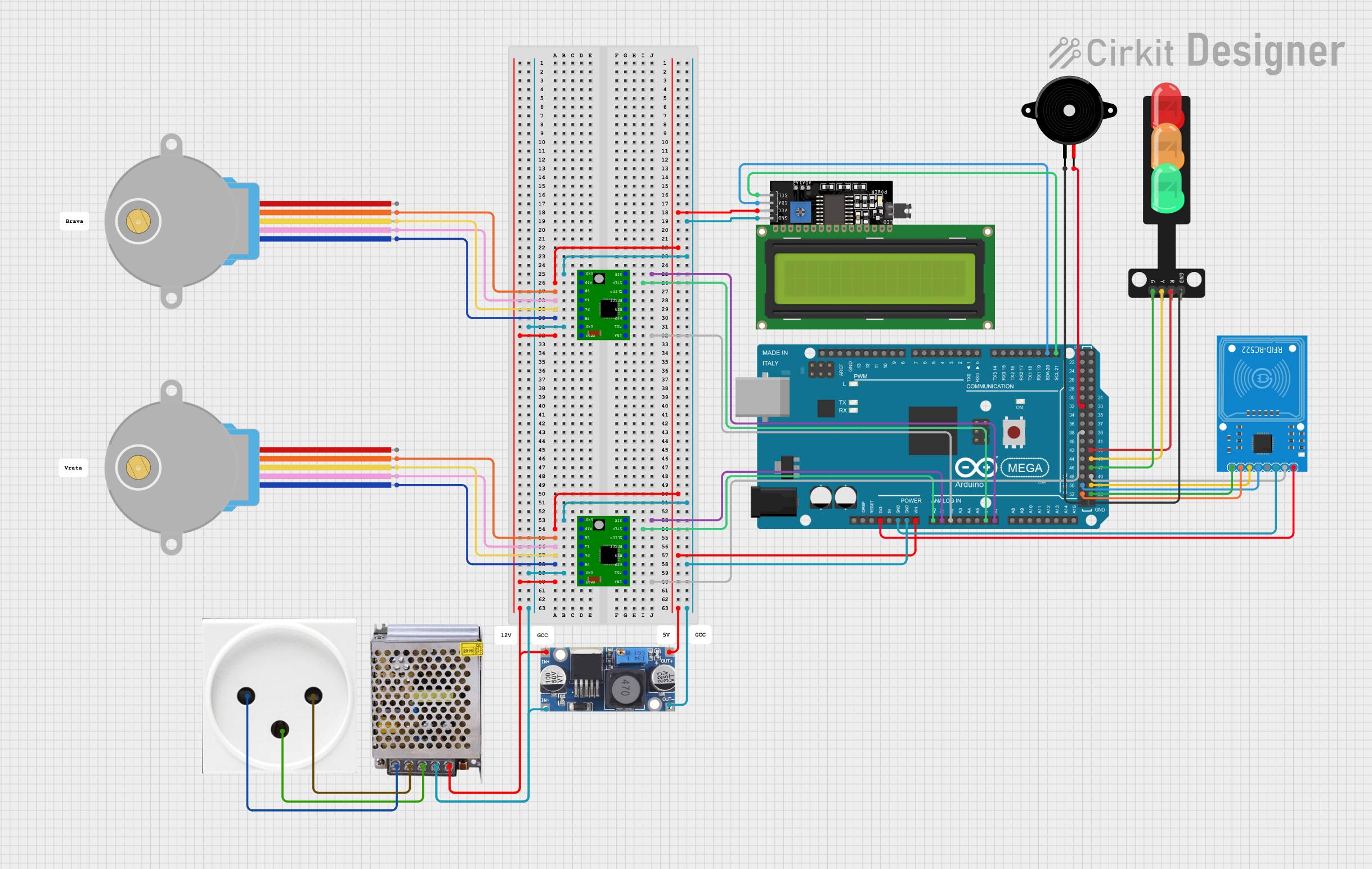
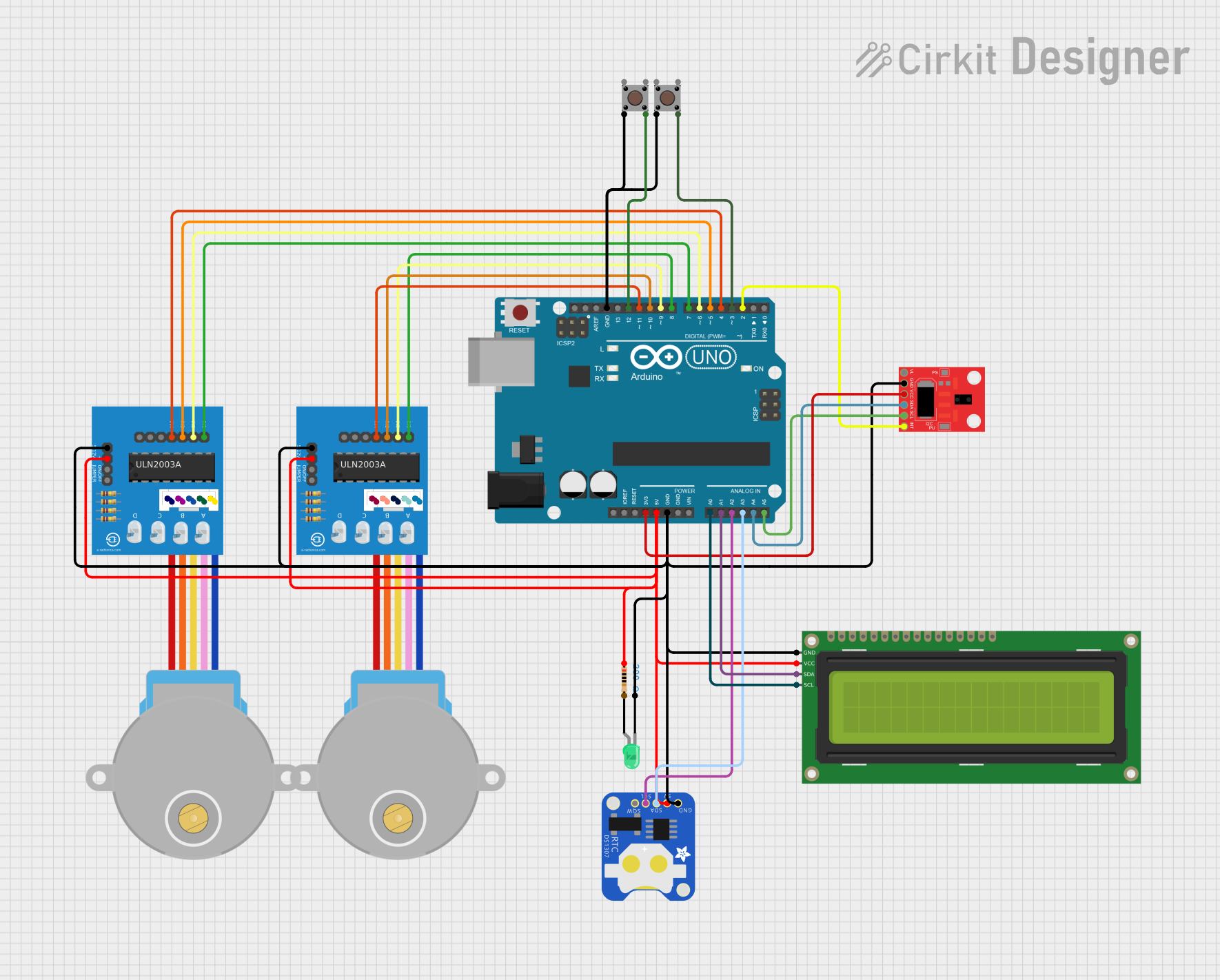
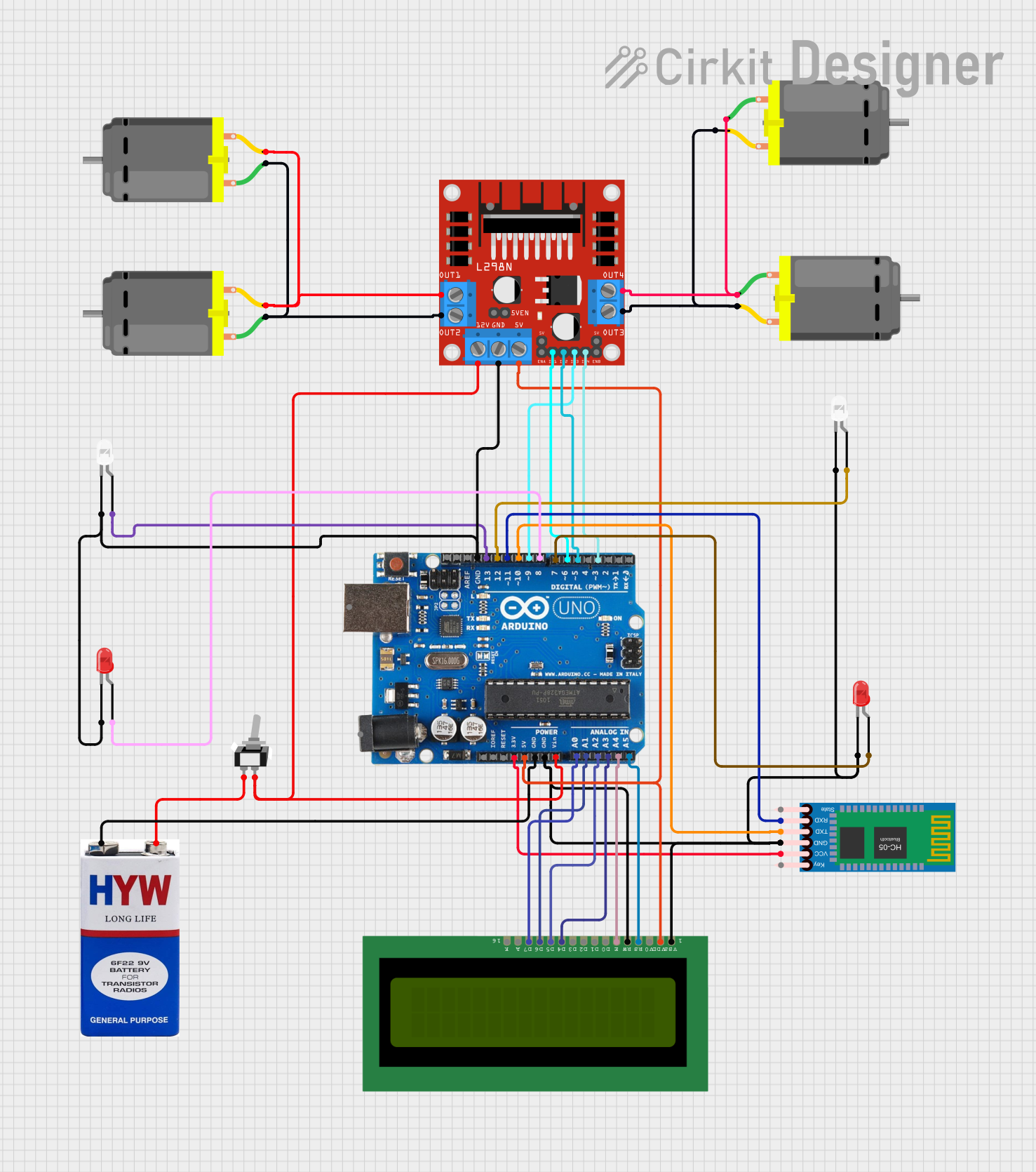
Explore Projects Built with Polulu DRV 8874
Common Applications
- Robotics and automation systems
- Electric vehicles and drones
- Conveyor belts and industrial machinery
- DIY projects involving DC or stepper motors
- Prototyping motor control circuits
Technical Specifications
The following table outlines the key technical details of the Pololu DRV8874 motor driver:
| Parameter | Value |
|---|---|
| Operating Voltage Range | 4.5V to 37V |
| Continuous Current per Channel | 3A |
| Peak Current per Channel | 6A (for short durations) |
| Control Interface | PWM, DIR (direction control) |
| Current Limiting Range | Adjustable via potentiometer |
| Logic Voltage Range | 1.8V to 5.5V |
| Built-in Protections | Overcurrent, overtemperature, undervoltage lockout |
| Dimensions | 1.0" × 0.8" × 0.2" (25mm × 20mm × 5mm) |
| Weight | 1.5g |
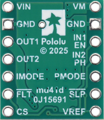
Pin Configuration and Descriptions
The Pololu DRV8874 features a 12-pin interface. The table below describes each pin:
| Pin Name | Type | Description |
|---|---|---|
| VIN | Power Input | Motor power supply input (4.5V to 37V). |
| GND | Power Ground | Ground connection for the motor power supply. |
| OUT1 | Output | Motor output 1. Connect to one terminal of the motor. |
| OUT2 | Output | Motor output 2. Connect to the other terminal of the motor. |
| VCC | Power Input | Logic power supply input (1.8V to 5.5V). |
| GND | Power Ground | Ground connection for the logic power supply. |
| PWM | Input | PWM signal input for speed control. |
| DIR | Input | Direction control input. |
| nFAULT | Output | Fault indicator (active low). |
| nSLEEP | Input | Sleep mode control (active low). |
| VREF | Input | Reference voltage for current limiting. |
| MODE | Input | Mode selection for controlling DC or stepper motors. |
Usage Instructions
How to Use the Pololu DRV8874 in a Circuit
Power Connections:
- Connect the motor power supply to the
VINpin and ground to theGNDpin. - Connect the logic power supply (e.g., 5V from a microcontroller) to the
VCCpin and its ground to theGNDpin.
- Connect the motor power supply to the
Motor Connections:
- Connect the motor terminals to the
OUT1andOUT2pins.
- Connect the motor terminals to the
Control Signals:
- Use the
PWMpin to control the motor speed by providing a PWM signal. - Use the
DIRpin to set the motor's direction (HIGH for one direction, LOW for the other).
- Use the
Current Limiting:
- Adjust the current limit by setting the
VREFvoltage. Refer to the datasheet for the formula to calculate the current limit.
- Adjust the current limit by setting the
Sleep Mode:
- To reduce power consumption, pull the
nSLEEPpin LOW to put the driver into sleep mode.
- To reduce power consumption, pull the
Fault Monitoring:
- Monitor the
nFAULTpin to detect issues such as overcurrent or overtemperature conditions.
- Monitor the
Example: Connecting to an Arduino UNO
Below is an example of how to control a DC motor using the Pololu DRV8874 and an Arduino UNO:
// Define pin connections
const int pwmPin = 9;    // PWM pin connected to DRV8874 PWM
const int dirPin = 8;    // Direction pin connected to DRV8874 DIR
const int sleepPin = 7;  // Sleep pin connected to DRV8874 nSLEEP

void setup() {
  // Set pin modes
  pinMode(pwmPin, OUTPUT);
  pinMode(dirPin, OUTPUT);
  pinMode(sleepPin, OUTPUT);

  // Wake up the motor driver
  digitalWrite(sleepPin, HIGH); // Set nSLEEP HIGH to enable the driver
}

void loop() {
  // Set motor direction
  digitalWrite(dirPin, HIGH); // HIGH for forward, LOW for reverse

  // Set motor speed
  analogWrite(pwmPin, 128); // 50% duty cycle (range: 0-255)

  delay(2000); // Run motor for 2 seconds

  // Stop the motor
  analogWrite(pwmPin, 0); // Set PWM to 0 to stop the motor

  delay(2000); // Wait for 2 seconds
}
Important Considerations
- Ensure the motor power supply voltage is within the specified range (4.5V to 37V).
- Avoid exceeding the continuous current rating of 3A to prevent damage.
- Use proper heat dissipation methods if operating near the maximum current limit.
- Double-check all connections before powering the circuit to avoid short circuits.
Troubleshooting and FAQs
Common Issues and Solutions
Motor Not Spinning:
- Verify that the
nSLEEPpin is set HIGH to enable the driver. - Check the
PWMsignal and ensure it is not set to 0. - Confirm that the motor power supply is connected and within the specified voltage range.
- Verify that the
Driver Overheating:
- Ensure the current limit is set appropriately using the
VREFpin. - Add a heatsink or improve ventilation if operating at high currents.
- Ensure the current limit is set appropriately using the
nFAULT Pin is LOW:
- This indicates a fault condition. Check for overcurrent, overtemperature, or undervoltage issues.
- Reduce the load on the motor or adjust the current limit.
Motor Spins in the Wrong Direction:
- Reverse the logic level on the
DIRpin or swap the motor connections onOUT1andOUT2.
- Reverse the logic level on the
FAQs
Q: Can the DRV8874 drive stepper motors?
A: Yes, the DRV8874 can drive stepper motors in full-step or microstepping modes. Use the MODE pin to configure the driver for stepper motor control.
Q: What happens if the current exceeds the limit?
A: The driver will enter current limiting mode to protect itself and the motor. Prolonged overcurrent conditions may trigger a fault.
Q: Is the DRV8874 compatible with 3.3V logic?
A: Yes, the driver supports logic levels from 1.8V to 5.5V, making it compatible with 3.3V and 5V systems.
Q: Can I use the DRV8874 with a battery-powered system?
A: Yes, as long as the battery voltage is within the operating range (4.5V to 37V).