How to Use DC MOTOR SPEED CONTROLLER: Examples, Pinouts, and Specs
Introduction
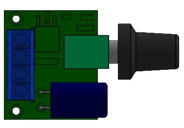
A DC Motor Speed Controller is a device used to regulate the speed of a DC motor by adjusting the voltage or current supplied to the motor. This allows for precise control of motor performance, making it an essential component in various applications.
Explore Projects Built with DC MOTOR SPEED CONTROLLER


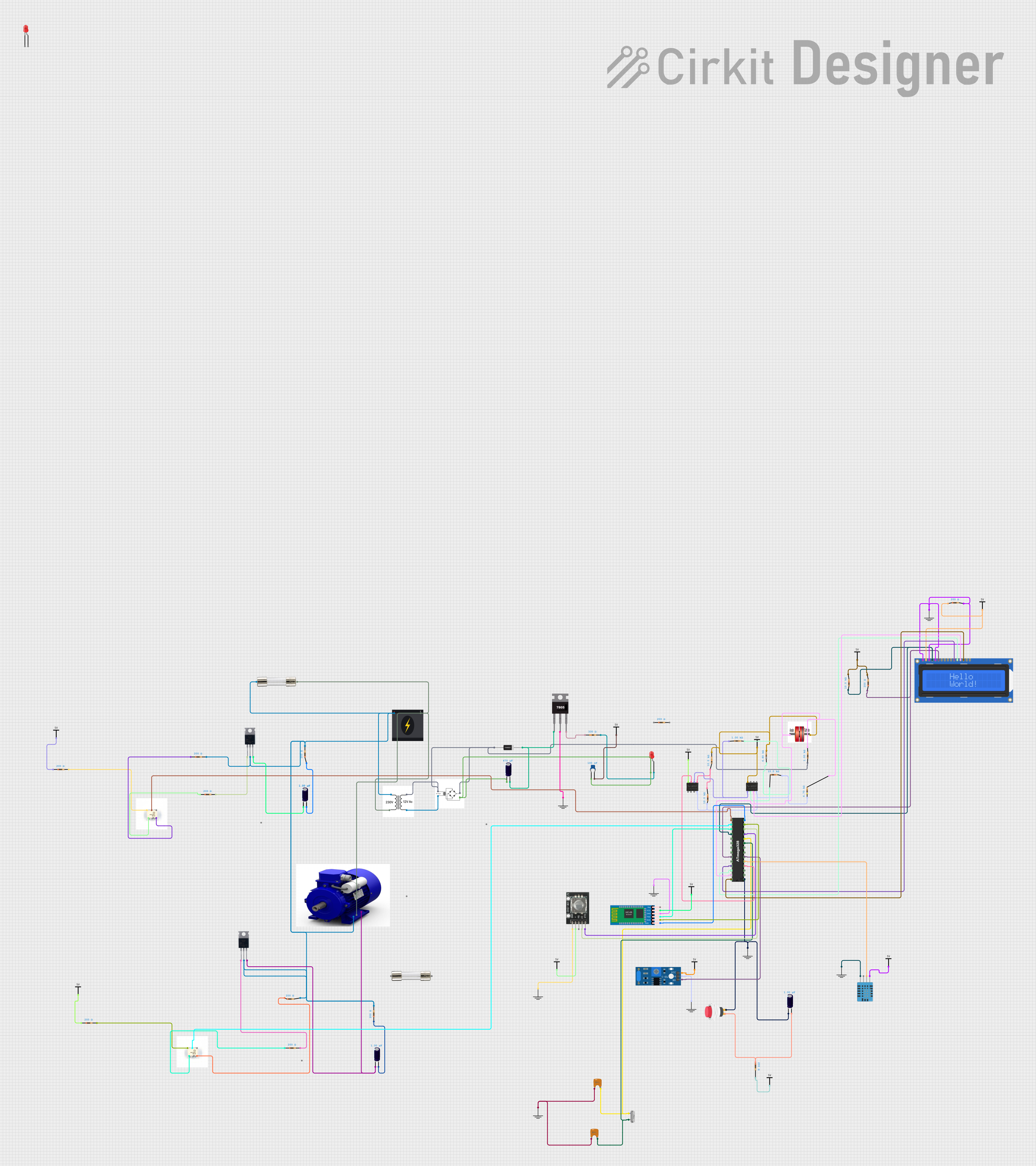
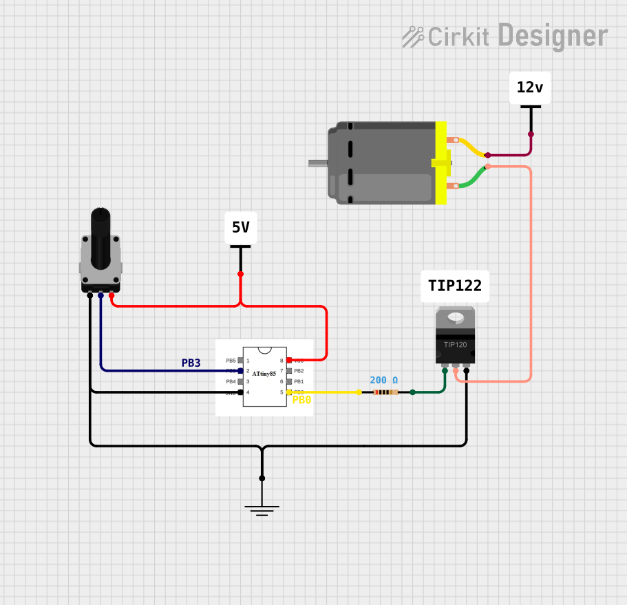
Explore Projects Built with DC MOTOR SPEED CONTROLLER
Common Applications and Use Cases
- Robotics: Controlling motor speed for precise movement.
- Electric vehicles: Adjusting motor speed for acceleration and deceleration.
- Industrial automation: Regulating conveyor belt speeds.
- Fans and pumps: Adjusting airflow or fluid flow rates.
- DIY projects: Custom motor control for hobbyist applications.
Technical Specifications
Below are the general technical specifications for a typical DC Motor Speed Controller. Note that specific models may vary, so always refer to the datasheet of your specific controller.
Key Technical Details
- Input Voltage Range: 6V to 30V DC (varies by model)
- Output Current: Up to 10A (check your model for exact limits)
- Control Method: Pulse Width Modulation (PWM)
- PWM Frequency: 1 kHz to 20 kHz
- Speed Adjustment Range: 0% to 100%
- Efficiency: ≥ 90%
- Operating Temperature: -20°C to 60°C
Pin Configuration and Descriptions
The following table describes the typical pin configuration for a DC Motor Speed Controller:
| Pin Name | Description |
|---|---|
| VIN+ | Positive input voltage terminal (connect to the power supply's positive terminal). |
| VIN- | Negative input voltage terminal (connect to the power supply's ground). |
| M+ | Positive motor terminal (connect to the motor's positive lead). |
| M- | Negative motor terminal (connect to the motor's negative lead). |
| PWM Input | Optional input for external PWM signal (if supported by the controller). |
| Potentiometer | Connects to the onboard potentiometer for manual speed adjustment. |
Usage Instructions
How to Use the Component in a Circuit
Connect the Power Supply:
- Connect the positive terminal of your DC power supply to the
VIN+pin. - Connect the ground terminal of your DC power supply to the
VIN-pin. - Ensure the power supply voltage is within the controller's input voltage range.
- Connect the positive terminal of your DC power supply to the
Connect the DC Motor:
- Connect the motor's positive lead to the
M+pin. - Connect the motor's negative lead to the
M-pin.
- Connect the motor's positive lead to the
Adjust the Speed:
- Use the onboard potentiometer to manually adjust the motor speed.
- Alternatively, if the controller supports external PWM input, connect a PWM signal to the
PWM Inputpin for precise speed control.
Power On:
- Turn on the power supply and observe the motor's behavior.
- Adjust the potentiometer or PWM signal to control the motor speed.
Important Considerations and Best Practices
- Current Rating: Ensure the motor's current draw does not exceed the controller's maximum current rating.
- Heat Dissipation: If the controller operates at high currents, ensure proper heat dissipation (e.g., use a heatsink or fan).
- Reverse Polarity Protection: Verify the polarity of your connections to avoid damaging the controller.
- PWM Signal: If using an external PWM signal, ensure the frequency and voltage levels are compatible with the controller.
Example: Using with an Arduino UNO
To control the speed of a DC motor using an Arduino UNO and a DC Motor Speed Controller with a PWM input, follow these steps:
Circuit Connections
- Connect the
VIN+andVIN-pins of the controller to a 12V DC power supply. - Connect the motor to the
M+andM-pins of the controller. - Connect the
PWM Inputpin of the controller to Arduino pin 9 (PWM-capable pin). - Connect the ground of the controller to the Arduino's GND pin.
Arduino Code
// DC Motor Speed Control using Arduino and PWM
// Connect the PWM input of the motor controller to Arduino pin 9.

const int pwmPin = 9; // PWM pin connected to the motor controller

void setup() {
  pinMode(pwmPin, OUTPUT); // Set the PWM pin as an output
}

void loop() {
  // Gradually increase motor speed
  for (int speed = 0; speed <= 255; speed++) {
    analogWrite(pwmPin, speed); // Write PWM signal to the controller
    delay(20); // Wait 20ms for smooth acceleration
  }

  // Gradually decrease motor speed
  for (int speed = 255; speed >= 0; speed--) {
    analogWrite(pwmPin, speed); // Write PWM signal to the controller
    delay(20); // Wait 20ms for smooth deceleration
  }
}
Troubleshooting and FAQs
Common Issues and Solutions
Motor Does Not Spin:
- Check all connections for proper polarity and secure attachment.
- Verify that the power supply voltage is within the controller's input range.
- Ensure the motor is functional by testing it directly with the power supply.
Motor Speed is Erratic:
- Check for loose connections or damaged wires.
- If using an external PWM signal, ensure the frequency and duty cycle are stable.
Controller Overheats:
- Ensure the motor's current draw does not exceed the controller's rating.
- Add a heatsink or cooling fan to the controller if necessary.
PWM Input Not Working:
- Verify that the PWM signal voltage and frequency are compatible with the controller.
- Check the Arduino code for errors and ensure the correct pin is used.
FAQs
Q: Can I use this controller with a brushless DC motor?
A: No, this controller is designed for brushed DC motors. Brushless motors require a dedicated brushless motor controller.
Q: What happens if I reverse the power supply polarity?
A: Reversing the polarity may damage the controller. Use a power supply with reverse polarity protection or double-check connections before powering on.
Q: Can I control multiple motors with one controller?
A: No, each motor requires its own controller to ensure proper operation and avoid overloading the controller.
Q: What is the advantage of using PWM for speed control?
A: PWM allows for efficient speed control by varying the duty cycle of the voltage applied to the motor, minimizing energy loss as heat.
This concludes the documentation for the DC Motor Speed Controller. Always refer to the specific datasheet of your controller for additional details.