
How to Use SI1120: Examples, Pinouts, and Specs
 Design with SI1120 in Cirkit Designer
Introduction
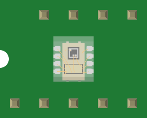
The SI1120 is a digital ambient light and proximity sensor designed to provide accurate light measurements and proximity detection. It features an I2C interface, enabling seamless integration into a wide range of electronic devices. With its compact design and high precision, the SI1120 is commonly used in applications such as smartphones, tablets, laptops, and other consumer electronics. It is particularly useful for optimizing display brightness and detecting nearby objects.
Explore Projects Built with SI1120
 Open Project in Cirkit Designer
 Open Project in Cirkit Designer
 Open Project in Cirkit Designer
 Open Project in Cirkit Designer
Explore Projects Built with SI1120
Open Project in Cirkit DesignerOpen Project in Cirkit DesignerOpen Project in Cirkit DesignerOpen Project in Cirkit DesignerTechnical Specifications
The SI1120 offers robust performance and flexibility for various applications. Below are its key technical details:
Key Specifications
| Parameter | Value |
|---|---|
| Supply Voltage (VDD) | 2.2V to 3.6V |
| Operating Current | 1.8 mA (typical) |
| Standby Current | 1 µA (typical) |
| Proximity Detection Range | Up to 50 cm |
| Ambient Light Range | 0.01 lux to 128,000 lux |
| Communication Interface | I2C (7-bit address) |
| Operating Temperature | -40°C to +85°C |
| Package Type | 10-pin DFN (3 mm x 3 mm) |
Pin Configuration and Descriptions
The SI1120 comes in a 10-pin DFN package. Below is the pinout and description:
| Pin Number | Pin Name | Description |
|---|---|---|
| 1 | VDD | Power supply input (2.2V to 3.6V). |
| 2 | GND | Ground connection. |
| 3 | SDA | I2C data line. |
| 4 | SCL | I2C clock line. |
| 5 | INT | Interrupt output (active low). |
| 6 | LED_DRV | LED driver output for proximity sensing. |
| 7 | NC | No connection (leave unconnected). |
| 8 | NC | No connection (leave unconnected). |
| 9 | NC | No connection (leave unconnected). |
| 10 | NC | No connection (leave unconnected). |
Usage Instructions
The SI1120 is straightforward to use in a circuit, thanks to its I2C interface. Below are the steps and considerations for integrating the sensor:
Circuit Connection
- Power Supply: Connect the VDD pin to a 2.2V to 3.6V power source and the GND pin to ground.
- I2C Interface: Connect the SDA and SCL pins to the corresponding I2C data and clock lines of your microcontroller. Use pull-up resistors (typically 4.7 kΩ) on both lines.
- Interrupt Pin: Optionally, connect the INT pin to a GPIO pin on your microcontroller to handle interrupts.
- LED Driver: If using the proximity sensing feature, connect an external IR LED to the LED_DRV pin.
Example Code for Arduino UNO
Below is an example of how to interface the SI1120 with an Arduino UNO using the Wire library:
#include <Wire.h>

#define SI1120_I2C_ADDRESS 0x52  // Replace with the actual 7-bit I2C address

void setup() {
  Wire.begin();  // Initialize I2C communication
  Serial.begin(9600);  // Initialize serial communication for debugging

  // Configure the SI1120 (example: enable proximity sensing)
  Wire.beginTransmission(SI1120_I2C_ADDRESS);
  Wire.write(0x01);  // Write to a configuration register (example address)
  Wire.write(0x03);  // Example configuration value
  Wire.endTransmission();

  Serial.println("SI1120 initialized.");
}

void loop() {
  // Request proximity data from the SI1120
  Wire.beginTransmission(SI1120_I2C_ADDRESS);
  Wire.write(0x02);  // Register address for proximity data
  Wire.endTransmission();

  Wire.requestFrom(SI1120_I2C_ADDRESS, 1);  // Request 1 byte of data
  if (Wire.available()) {
    uint8_t proximity = Wire.read();  // Read proximity data
    Serial.print("Proximity: ");
    Serial.println(proximity);
  }

  delay(500);  // Wait 500 ms before the next reading
}
Best Practices
- Use decoupling capacitors (e.g., 0.1 µF) near the VDD pin to stabilize the power supply.
- Ensure proper pull-up resistors are used on the I2C lines.
- Avoid placing the sensor near strong light sources or reflective surfaces to prevent inaccurate readings.
- If using the proximity sensing feature, position the IR LED close to the sensor for optimal performance.
Troubleshooting and FAQs
Common Issues
No I2C Communication:
- Cause: Incorrect wiring or missing pull-up resistors.
- Solution: Verify the SDA and SCL connections and ensure pull-up resistors are present.
Inaccurate Light Measurements:
- Cause: Sensor exposed to direct sunlight or reflective surfaces.
- Solution: Shield the sensor from direct light or reposition it.
Proximity Detection Not Working:
- Cause: IR LED not connected or improperly positioned.
- Solution: Check the LED connection and ensure it is aligned with the sensor.
Interrupt Pin Not Responding:
- Cause: Interrupts not enabled in the sensor configuration.
- Solution: Verify the sensor's configuration registers and enable interrupts.
FAQs
Q: What is the maximum I2C clock speed supported by the SI1120?
A: The SI1120 supports I2C clock speeds up to 400 kHz (Fast Mode).
Q: Can the SI1120 measure both ambient light and proximity simultaneously?
A: Yes, the SI1120 can perform both measurements simultaneously, but ensure proper configuration of its registers.
Q: Is the SI1120 compatible with 5V microcontrollers?
A: The SI1120 operates at 2.2V to 3.6V. Use a level shifter if interfacing with a 5V microcontroller.
Q: How do I calculate lux from the raw ambient light data?
A: Refer to the SI1120 datasheet for the specific formula to convert raw data to lux, as it depends on the sensor's calibration.
By following this documentation, users can effectively integrate and utilize the SI1120 in their projects.