How to Use Adafruit Si4713 Stereo FM Transmitter: Examples, Pinouts, and Specs
Introduction
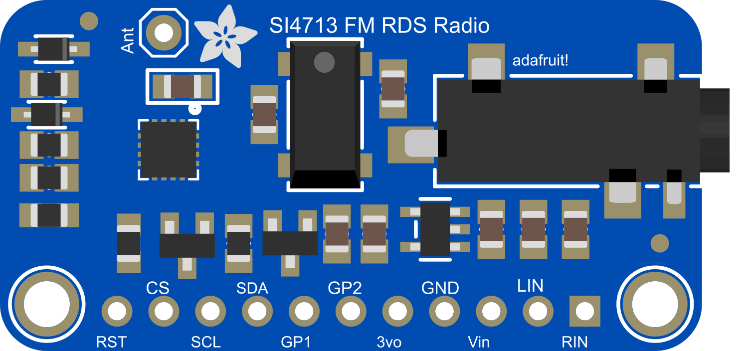
The Adafruit Si4713 Stereo FM Transmitter is a compact, highly integrated FM radio transmitter module capable of broadcasting high-quality stereo audio signals. It is designed for use in a wide range of applications, including personal radio broadcasting, consumer electronics, and educational projects. The module is based on the Si4713 IC from Silicon Labs and offers an adjustable output power to cater to various transmission distances.
Explore Projects Built with Adafruit Si4713 Stereo FM Transmitter

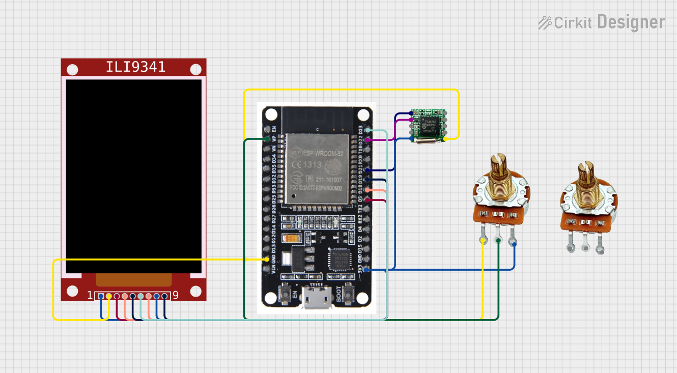
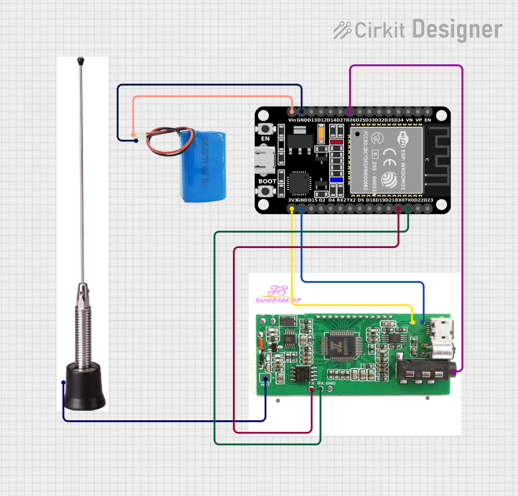
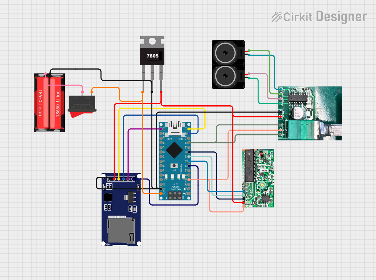
Explore Projects Built with Adafruit Si4713 Stereo FM Transmitter
Common Applications and Use Cases
- Personal FM radio stations
- Wireless audio for events or installations
- Educational projects in RF communications
- Prototyping consumer electronics with FM broadcasting capabilities
Technical Specifications
Key Technical Details
- Frequency Range: 76 MHz to 108 MHz (FM band)
- Output Power: Adjustable up to 115 dBuV
- Audio Input: Stereo line level (3.5mm jack)
- Supply Voltage: 3.3V to 5V DC
- Current Consumption: 40mA (typical at 3.3V)
- Communication Interface: I2C
- Antenna Output: Single wire antenna
Pin Configuration and Descriptions
| Pin Number | Name | Description |
|---|---|---|
| 1 | GND | Ground connection |
| 2 | VIN | Supply voltage (3.3V to 5V DC) |
| 3 | SCL | I2C clock line |
| 4 | SDA | I2C data line |
| 5 | RST | Reset pin (active low) |
| 6 | GPIO | General-purpose input/output (configurable) |
| 7 | ANT | Antenna output (for single wire antenna) |
| 8 | L-IN | Left channel audio input |
| 9 | R-IN | Right channel audio input |
| 10 | GPO1 | General-purpose output (configurable) |
Usage Instructions
How to Use the Component in a Circuit
- Power Supply: Connect the VIN pin to a 3.3V to 5V power supply and the GND pin to the ground.
- Audio Input: Connect the left and right audio sources to the L-IN and R-IN pins, respectively.
- Antenna: Attach a single wire antenna to the ANT pin for signal transmission.
- I2C Communication: Connect the SCL and SDA pins to the corresponding I2C clock and data lines on your microcontroller (e.g., Arduino UNO).
- Reset (Optional): Connect the RST pin to a digital output on your microcontroller if you wish to control the reset function programmatically.
Important Considerations and Best Practices
- Ensure that the power supply is within the specified voltage range to prevent damage.
- Use a proper antenna to comply with local regulations regarding FM transmission.
- Keep the audio input levels within the line level range to avoid distortion.
- Follow I2C pull-up resistor guidelines when connecting to a microcontroller.
- Avoid placing the transmitter near metal objects or electronic devices that may interfere with the signal.
Example Code for Arduino UNO
#include <Wire.h>
#include "Adafruit_Si4713.h"

Adafruit_Si4713 fmTransmitter = Adafruit_Si4713();

void setup() {
  Serial.begin(9600);
  // Start communication with FM transmitter
  if (!fmTransmitter.begin()) {
    Serial.println("Failed to find Si4713 FM transmitter");
    while (1);
  }
  fmTransmitter.setTXpower(115); // Set maximum transmission power
  fmTransmitter.setFrequency(1013); // Set frequency to 101.3 MHz
}

void loop() {
  // Main loop can be used to update audio inputs or change frequencies
}
Troubleshooting and FAQs
Common Issues Users Might Face
- No Signal: Ensure the antenna is properly connected and the frequency is set within the FM band.
- Poor Audio Quality: Check the audio input levels and wiring. Use shielded cables if possible.
- Interference: Try changing the transmission frequency or relocating the transmitter away from other electronic devices.
Solutions and Tips for Troubleshooting
- Reset the Module: If the module is unresponsive, use the RST pin to reset it.
- Check Power Supply: Verify that the power supply is stable and within the required voltage range.
- I2C Communication: Ensure that the I2C lines are properly connected and that there are pull-up resistors in place.
FAQs
Q: Can I use this transmitter to broadcast over long distances? A: The transmission range is subject to local regulations and environmental factors. The module is designed for short-range broadcasting; for longer distances, additional equipment and licensing may be required.
Q: Is it legal to use this FM transmitter? A: FM transmission legality varies by country and region. Always check and comply with local laws regarding FM broadcasting.
Q: How do I change the transmission frequency?
A: The transmission frequency can be set programmatically using the setFrequency() function in the provided library.
Q: What is the maximum audio input level for the Si4713? A: The Si4713 accepts standard line-level audio signals. Exceeding this level may result in distorted audio output.
Q: Can I use this module with a battery? A: Yes, as long as the battery provides a stable voltage within the 3.3V to 5V range and can supply the necessary current.