Cirkit Designer Logo
Cirkit Designer
Your all-in-one circuit design IDE
Home / 
Component Documentation

How to Use Adafruit 1.54inch 240x240 IPS TFT: Examples, Pinouts, and Specs

Image of Adafruit 1.54inch 240x240 IPS TFT
Cirkit Designer LogoDesign with Adafruit 1.54inch 240x240 IPS TFT in Cirkit Designer

Introduction

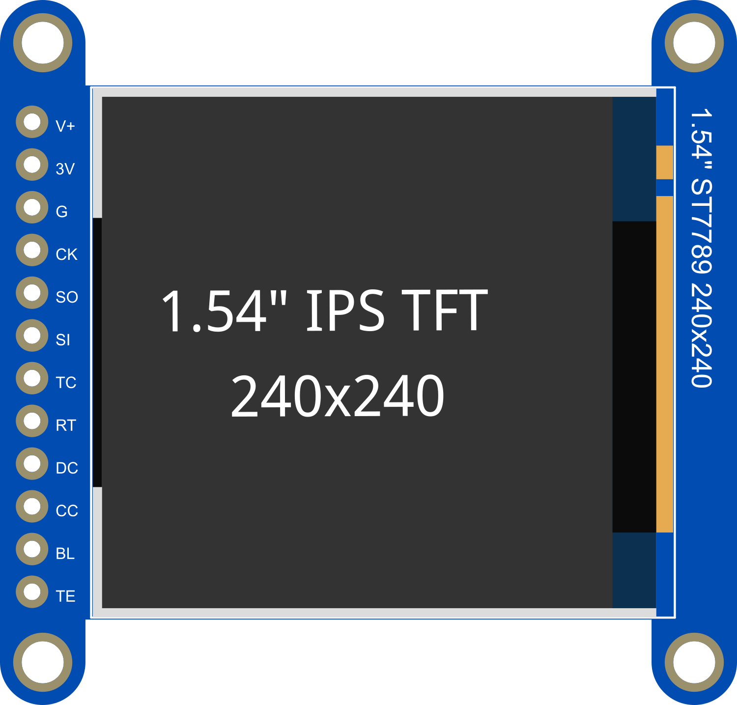
The Adafruit 1.54" 240x240 IPS TFT is a compact and vibrant display module suitable for adding a small but high-resolution color screen to your electronics projects. With In-Plane Switching (IPS) technology, it provides excellent viewing angles and consistent color representation. This display is commonly used in wearable devices, portable instruments, small embedded systems, and any application where a small, colorful, and bright display is needed.

Explore Projects Built with Adafruit 1.54inch 240x240 IPS TFT

Use Cirkit Designer to design, explore, and prototype these projects online. Some projects support real-time simulation. Click "Open Project" to start designing instantly!
Arduino Mega 2560 Controlled TFT Touchscreen Interface
Image of Tablero Moto: A project utilizing Adafruit 1.54inch 240x240 IPS TFT in a practical application
This circuit connects an Arduino Mega 2560 microcontroller to a 3.5-inch 480x320 TFT LCD display. The Arduino provides power, ground, and digital signals to control the display, including data lines for pixel information and control lines for reset, write, and command/data selection. The embedded code initializes the display and configures the Arduino's pins for communication, likely to create a user interface or visual output for a project.
Cirkit Designer LogoOpen Project in Cirkit Designer
ESP32-Powered 1.3 inch TFT Display Module for Visual Data Output
Image of ESP32+ST7789: A project utilizing Adafruit 1.54inch 240x240 IPS TFT in a practical application
This circuit connects an ESP32 microcontroller to a 1.3 inch TFT display module (ST7789). The ESP32 provides power and control signals to the display, enabling it to show graphical data.
Cirkit Designer LogoOpen Project in Cirkit Designer
Arduino Nano Controlled TFT Display with Multiple Pushbuttons
Image of rey: A project utilizing Adafruit 1.54inch 240x240 IPS TFT in a practical application
This circuit features an Arduino Nano microcontroller connected to a ST7735 128x128 1.44 TFT I2C Color display and multiple pushbuttons. The display is interfaced with the Arduino via digital pins for control signals and SPI pins for data transfer. The pushbuttons are connected to various digital and analog input pins on the Arduino, likely intended for user input to control the display or other functions within the code.
Cirkit Designer LogoOpen Project in Cirkit Designer
Arduino UNO and ILI9341 TFT Display Interactive Graphics Demo
Image of CE Test ili9341: A project utilizing Adafruit 1.54inch 240x240 IPS TFT in a practical application
This circuit interfaces an Arduino UNO with an ILI9341 TFT display using two bi-directional logic level converters to manage voltage differences. The Arduino runs a program to test various graphical functions on the TFT display, demonstrating its capabilities through a series of visual benchmarks.
Cirkit Designer LogoOpen Project in Cirkit Designer

Explore Projects Built with Adafruit 1.54inch 240x240 IPS TFT

Use Cirkit Designer to design, explore, and prototype these projects online. Some projects support real-time simulation. Click "Open Project" to start designing instantly!
Image of Tablero Moto: A project utilizing Adafruit 1.54inch 240x240 IPS TFT in a practical application
Arduino Mega 2560 Controlled TFT Touchscreen Interface
This circuit connects an Arduino Mega 2560 microcontroller to a 3.5-inch 480x320 TFT LCD display. The Arduino provides power, ground, and digital signals to control the display, including data lines for pixel information and control lines for reset, write, and command/data selection. The embedded code initializes the display and configures the Arduino's pins for communication, likely to create a user interface or visual output for a project.
Cirkit Designer LogoOpen Project in Cirkit Designer
Image of ESP32+ST7789: A project utilizing Adafruit 1.54inch 240x240 IPS TFT in a practical application
ESP32-Powered 1.3 inch TFT Display Module for Visual Data Output
This circuit connects an ESP32 microcontroller to a 1.3 inch TFT display module (ST7789). The ESP32 provides power and control signals to the display, enabling it to show graphical data.
Cirkit Designer LogoOpen Project in Cirkit Designer
Image of rey: A project utilizing Adafruit 1.54inch 240x240 IPS TFT in a practical application
Arduino Nano Controlled TFT Display with Multiple Pushbuttons
This circuit features an Arduino Nano microcontroller connected to a ST7735 128x128 1.44 TFT I2C Color display and multiple pushbuttons. The display is interfaced with the Arduino via digital pins for control signals and SPI pins for data transfer. The pushbuttons are connected to various digital and analog input pins on the Arduino, likely intended for user input to control the display or other functions within the code.
Cirkit Designer LogoOpen Project in Cirkit Designer
Image of CE Test ili9341: A project utilizing Adafruit 1.54inch 240x240 IPS TFT in a practical application
Arduino UNO and ILI9341 TFT Display Interactive Graphics Demo
This circuit interfaces an Arduino UNO with an ILI9341 TFT display using two bi-directional logic level converters to manage voltage differences. The Arduino runs a program to test various graphical functions on the TFT display, demonstrating its capabilities through a series of visual benchmarks.
Cirkit Designer LogoOpen Project in Cirkit Designer

Technical Specifications

Key Features

  • Display Size: 1.54 inches
  • Resolution: 240x240 pixels
  • Interface: SPI (Serial Peripheral Interface)
  • Technology: IPS for wide viewing angles
  • Color Depth: 16-bit (65K colors)
  • Operating Voltage: 3.3V - 5V compatible
  • Logic Level: 3.3V

Pin Configuration

Pin Number Pin Name Description
1 GND Ground
2 VCC Power supply (3.3V - 5V)
3 SCL SPI clock
4 SDA SPI data input
5 RES Reset pin
6 DC Data/command control pin
7 CS Chip select for SPI
8 BL Backlight control (optional PWM input)

Usage Instructions

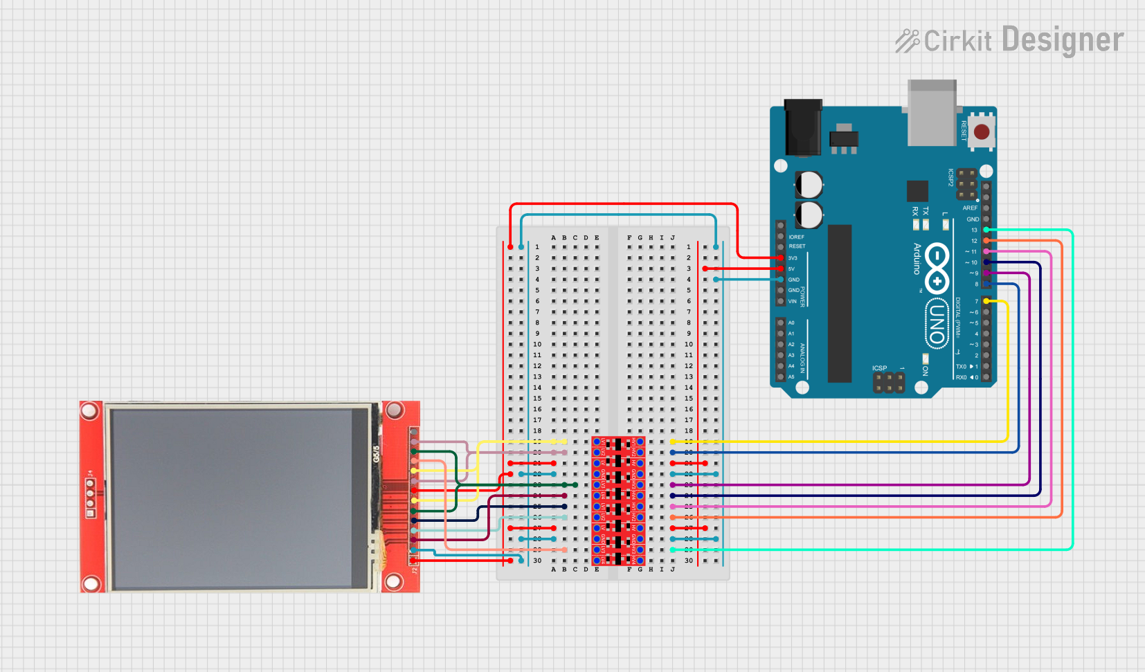
Wiring to an Arduino UNO

  1. Connect GND to the Arduino's ground pin.
  2. Connect VCC to the Arduino's 5V or 3.3V output.
  3. Connect SCL to the Arduino's SCK pin (Digital 13).
  4. Connect SDA to the Arduino's MOSI pin (Digital 11).
  5. Connect RES to a digital pin (e.g., Digital 9), for controlling the reset.
  6. Connect DC to another digital pin (e.g., Digital 8), for data/command selection.
  7. Connect CS to the Arduino's SS pin (Digital 10).
  8. Connect BL to a PWM pin if you wish to control the backlight brightness, or to VCC for always-on backlight.

Initializing the Display

To use the display with an Arduino, you will need to install the Adafruit GFX library and the Adafruit ST7789 library, which can be found in the Arduino Library Manager.

Here is a basic example of how to initialize the display:

#include <Adafruit_GFX.h>    // Core graphics library
#include <Adafruit_ST7789.h> // Hardware-specific library for ST7789

// Pin definitions
#define TFT_CS         10
#define TFT_RST        9  // Or set to -1 and connect to Arduino RESET pin
#define TFT_DC         8
#define TFT_MOSI       11 // Data out
#define TFT_SCLK       13 // Clock out

// Initialize Adafruit ST7789 TFT library
Adafruit_ST7789 tft = Adafruit_ST7789(TFT_CS, TFT_DC, TFT_MOSI, TFT_SCLK, TFT_RST);

void setup() {
  Serial.begin(9600);
  tft.init(240, 240);           // Initialize screen with its resolution
  tft.fillScreen(ST77XX_BLACK); // Clear the screen to black
}

void loop() {
  // Your code to update the display goes here
}

Best Practices

  • Always use a level shifter or logic level converter if you're interfacing with a 5V microcontroller.
  • Avoid exposing the display to direct sunlight for extended periods to prevent damage.
  • When writing to the display, minimize the number of screen updates to reduce flickering and improve performance.

Troubleshooting and FAQs

Common Issues

  • Screen not lighting up: Ensure that the wiring is correct and that the backlight pin (BL) is receiving power.
  • Garbled or no display: Check that the SPI connections are secure and that the correct pins are used for CS, DC, and RES.
  • Dim display: Verify that the backlight (BL) is connected properly and that the PWM value (if used) is set high enough.

FAQs

Q: Can I use this display with a 5V microcontroller? A: Yes, but ensure that the logic levels are compatible or use a level shifter.

Q: How can I control the backlight brightness? A: Connect the BL pin to a PWM-capable pin on your microcontroller and use analogWrite() to adjust the brightness.

Q: What libraries do I need to use this display with an Arduino? A: You will need the Adafruit GFX library and the Adafruit ST7789 library.

Q: Can I use this display in a battery-powered project? A: Yes, the display's low power consumption makes it suitable for battery-powered applications.

For further assistance, consult the Adafruit forums or the product's official documentation.