How to Use HT-HC01P Breakout Board: Examples, Pinouts, and Specs
Introduction
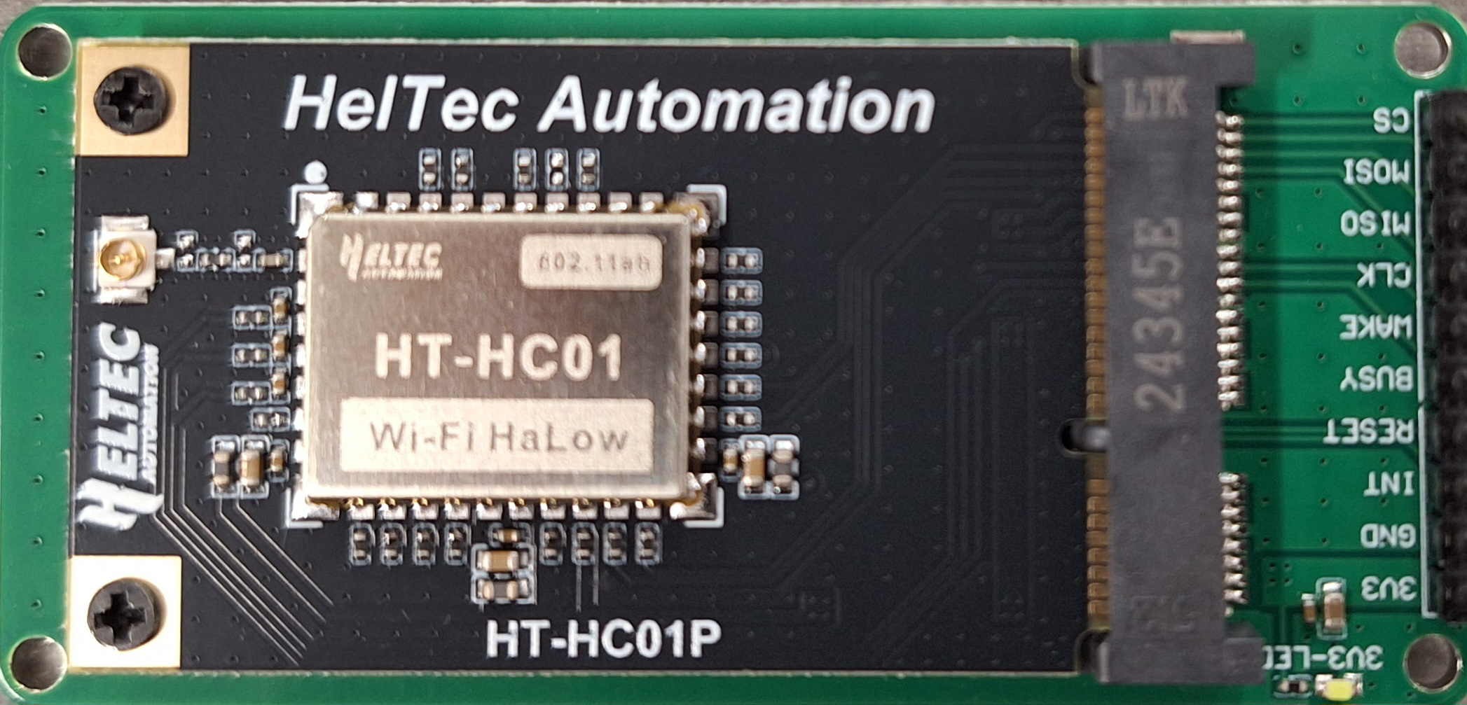
The HT-HC01P Breakout Board, manufactured by HelTec Automation (Part ID: HT-HC01P PCB), is a compact and user-friendly breakout board designed for the HC-01P Bluetooth module. It simplifies the process of interfacing with the HC-01P by providing easy access to its pins and enabling seamless connections for prototyping and development. This breakout board is ideal for wireless communication projects, IoT applications, and Bluetooth-enabled devices.
Explore Projects Built with HT-HC01P Breakout Board
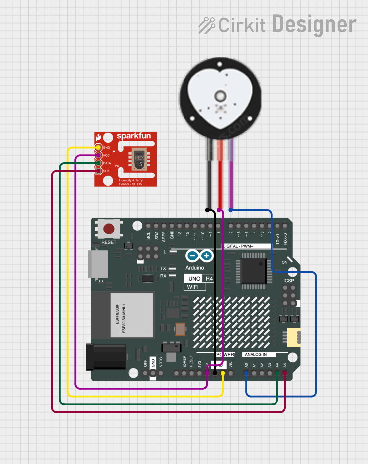
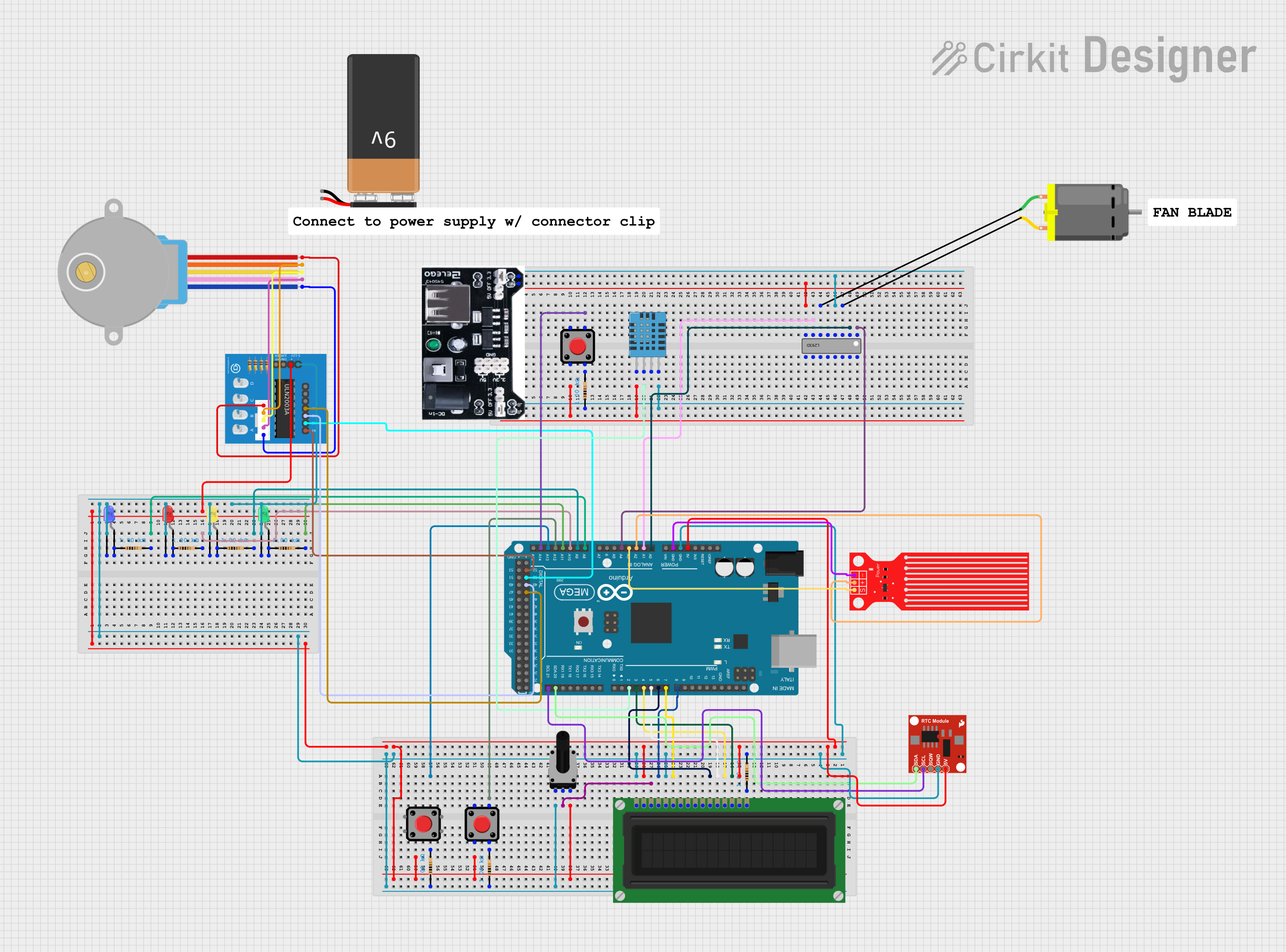

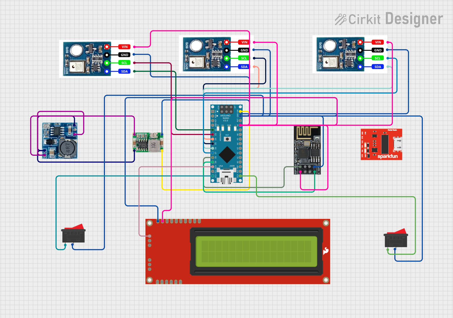
Explore Projects Built with HT-HC01P Breakout Board
Common Applications and Use Cases
- Wireless data transmission between devices
- IoT projects requiring Bluetooth connectivity
- Remote control systems
- Bluetooth-based sensor networks
- Prototyping and testing Bluetooth communication modules
Technical Specifications
The HT-HC01P Breakout Board is designed to work with the HC-01P Bluetooth module and provides the following technical features:
Key Technical Details
| Parameter | Specification |
|---|---|
| Operating Voltage | 3.3V to 5V |
| Communication Protocol | UART (Universal Asynchronous Receiver-Transmitter) |
| Baud Rate (Default) | 9600 bps |
| Dimensions | 25mm x 15mm x 3mm |
| Pin Pitch | 2.54mm (standard breadboard spacing) |
| Operating Temperature | -40°C to 85°C |
Pin Configuration and Descriptions
The breakout board exposes the following pins for easy interfacing:
| Pin Name | Direction | Description |
|---|---|---|
| VCC | Input | Power supply input (3.3V to 5V) |
| GND | Input | Ground connection |
| TXD | Output | UART Transmit pin (data sent from the module) |
| RXD | Input | UART Receive pin (data sent to the module) |
| EN | Input | Enable pin (active HIGH to enable the module) |
Usage Instructions
How to Use the Component in a Circuit
- Powering the Module: Connect the
VCCpin to a 3.3V or 5V power source and theGNDpin to ground. - UART Communication: Connect the
TXDpin of the breakout board to the RX pin of your microcontroller and theRXDpin to the TX pin of your microcontroller. - Enable the Module: Ensure the
ENpin is pulled HIGH to activate the module. You can connect it directly toVCCor control it via a GPIO pin on your microcontroller. - Bluetooth Pairing: Once powered, the HC-01P module will broadcast its Bluetooth signal. Use a Bluetooth-enabled device to search for and pair with the module.
Important Considerations and Best Practices
- Voltage Levels: Ensure that the UART pins (TXD and RXD) are compatible with the voltage levels of your microcontroller. Use a level shifter if necessary.
- Baud Rate: The default baud rate is 9600 bps. Ensure your microcontroller's UART settings match this value.
- Antenna Placement: Avoid placing the module near metal objects or inside enclosures that may block the Bluetooth signal.
- Power Supply: Use a stable power source to avoid communication issues caused by voltage fluctuations.
Example: Connecting to an Arduino UNO
Below is an example of how to connect the HT-HC01P Breakout Board to an Arduino UNO and send data via Bluetooth.
Wiring Diagram
| HT-HC01P Pin | Arduino UNO Pin |
|---|---|
| VCC | 5V |
| GND | GND |
| TXD | D2 (via voltage divider if needed) |
| RXD | D3 |
| EN | 5V |
Arduino Code
#include <SoftwareSerial.h>

// Define RX and TX pins for SoftwareSerial
SoftwareSerial bluetooth(2, 3); // RX = Pin 2, TX = Pin 3

void setup() {
  // Initialize serial communication for debugging
  Serial.begin(9600);
  // Initialize Bluetooth communication
  bluetooth.begin(9600);
  Serial.println("Bluetooth module ready. Waiting for data...");
}

void loop() {
  // Check if data is available from the Bluetooth module
  if (bluetooth.available()) {
    char received = bluetooth.read(); // Read the incoming data
    Serial.print("Received: ");
    Serial.println(received); // Print the received data to Serial Monitor
  }

  // Check if data is available from the Serial Monitor
  if (Serial.available()) {
    char toSend = Serial.read(); // Read the data from Serial Monitor
    bluetooth.write(toSend); // Send the data via Bluetooth
    Serial.print("Sent: ");
    Serial.println(toSend); // Print the sent data to Serial Monitor
  }
}
Troubleshooting and FAQs
Common Issues and Solutions
Module Not Powering On
- Cause: Incorrect power supply or loose connections.
- Solution: Verify that the
VCCandGNDpins are properly connected and the power supply is within the specified range (3.3V to 5V).
No Bluetooth Signal Detected
- Cause: The
ENpin is not pulled HIGH. - Solution: Ensure the
ENpin is connected toVCCor controlled via a GPIO pin set to HIGH.
- Cause: The
Communication Issues
- Cause: Mismatched baud rate or incorrect wiring.
- Solution: Confirm that the baud rate of the microcontroller matches the module's default baud rate (9600 bps). Double-check the TXD and RXD connections.
Weak Bluetooth Signal
- Cause: Interference or poor antenna placement.
- Solution: Relocate the module to a position with minimal interference and ensure it is not enclosed in a metal case.
FAQs
Q: Can I use the HT-HC01P Breakout Board with a 3.3V microcontroller?
A: Yes, the breakout board is compatible with both 3.3V and 5V systems. Ensure the UART voltage levels match your microcontroller.
Q: How do I change the baud rate of the HC-01P module?
A: The baud rate can be changed using AT commands. Refer to the HC-01P module's datasheet for detailed instructions.
Q: Is the breakout board compatible with other Bluetooth modules?
A: The HT-HC01P Breakout Board is specifically designed for the HC-01P module. Compatibility with other modules is not guaranteed.
Q: Can I use this module for audio transmission?
A: No, the HC-01P module is designed for data transmission only and does not support audio streaming.