
How to Use 1N4004 Rectifier Diode: Examples, Pinouts, and Specs

 Design with 1N4004 Rectifier Diode in Cirkit Designer
Introduction
The 1N4004 is a general-purpose silicon rectifier diode designed for applications requiring reliable rectification of AC to DC. It is capable of handling a maximum reverse voltage of 400V and a forward current of 1A. This diode is widely used in power supply circuits, voltage rectifiers, and protection circuits due to its robust design and ease of use.
Explore Projects Built with 1N4004 Rectifier Diode
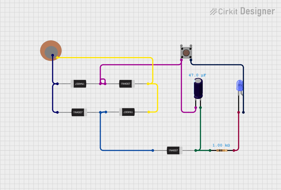 Open Project in Cirkit Designer
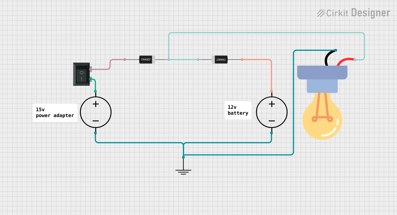 Open Project in Cirkit Designer
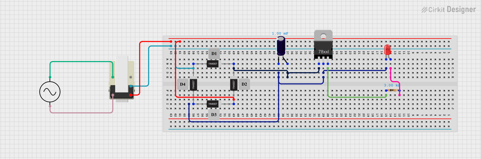 Open Project in Cirkit Designer
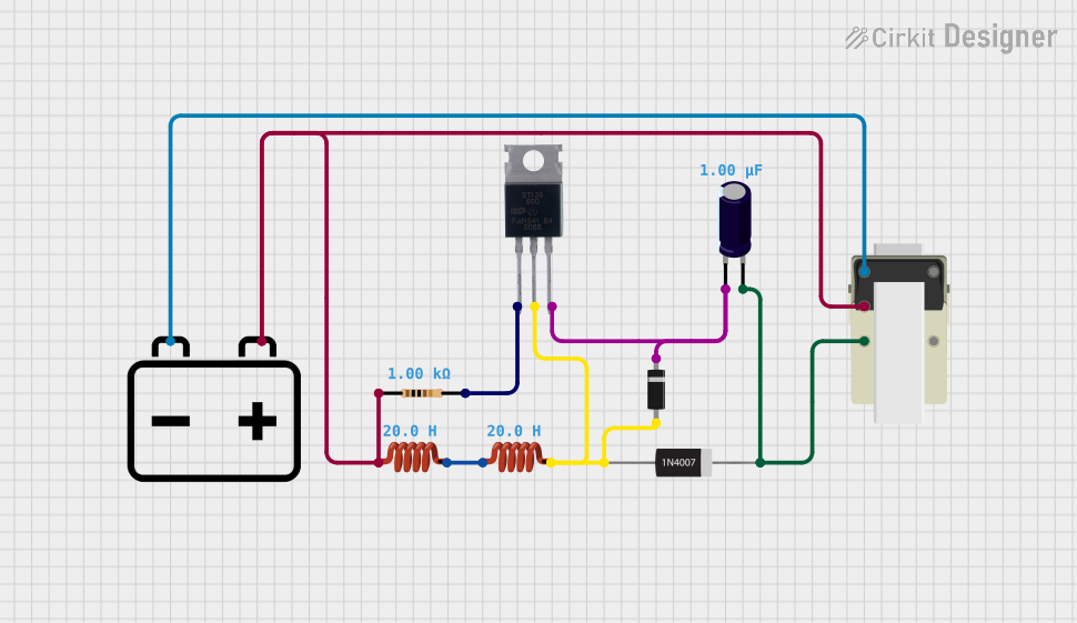 Open Project in Cirkit Designer
Explore Projects Built with 1N4004 Rectifier Diode
Open Project in Cirkit DesignerOpen Project in Cirkit DesignerOpen Project in Cirkit DesignerOpen Project in Cirkit DesignerCommon Applications:
- AC to DC conversion in power supplies
- Freewheeling diodes in inductive loads
- Reverse polarity protection in circuits
- Voltage clamping and surge protection
Technical Specifications
The following table outlines the key technical details of the 1N4004 rectifier diode:
| Parameter | Value |
|---|---|
| Maximum Reverse Voltage | 400V |
| Maximum Forward Current | 1A |
| Peak Surge Current | 30A (8.3ms single half-sine) |
| Forward Voltage Drop | 1.1V (at 1A) |
| Reverse Current | 5µA (at 25°C, 400V) |
| Operating Temperature | -65°C to +150°C |
| Package Type | DO-41 |
Pin Configuration:
The 1N4004 diode has two terminals:
| Pin | Description |
|---|---|
| Anode | Positive terminal (current enters) |
| Cathode | Negative terminal (current exits) |
The cathode is marked with a silver or white band on the diode body.
Usage Instructions
How to Use the 1N4004 in a Circuit:
- Identify the Terminals: Locate the cathode (marked with a silver/white band) and the anode.
- Connect in the Correct Orientation:
- For rectification, connect the anode to the positive side of the AC signal and the cathode to the load or DC output.
- For reverse polarity protection, connect the cathode to the positive terminal of the power supply and the anode to the circuit.
- Ensure Proper Ratings: Verify that the voltage and current in your circuit do not exceed the diode's maximum ratings (400V reverse voltage, 1A forward current).
- Add a Filter Capacitor (if needed): In rectifier circuits, use a capacitor across the load to smooth the DC output.
Example Circuit: AC to DC Rectification
Below is an example of using the 1N4004 diode in a full-wave rectifier circuit with an Arduino UNO:
Circuit Description:
- The 1N4004 diodes are used to convert an AC signal into a DC signal.
- A capacitor is added to smooth the output voltage.
Arduino Code for Monitoring DC Voltage:
// This code reads the DC voltage from the rectifier circuit using an Arduino UNO.
// The voltage is measured on analog pin A0 and displayed via the Serial Monitor.

const int analogPin = A0; // Pin connected to the rectifier output
float voltage = 0.0;      // Variable to store the measured voltage

void setup() {
  Serial.begin(9600); // Initialize serial communication at 9600 baud
}

void loop() {
  int sensorValue = analogRead(analogPin); // Read the analog input
  voltage = sensorValue * (5.0 / 1023.0); // Convert to voltage (5V reference)

  // Print the voltage to the Serial Monitor
  Serial.print("Measured Voltage: ");
  Serial.print(voltage);
  Serial.println(" V");

  delay(1000); // Wait for 1 second before the next reading
}
Important Considerations:
- Heat Dissipation: Ensure adequate ventilation or heat sinking if the diode operates near its maximum current rating.
- Surge Protection: Avoid exceeding the peak surge current rating (30A for 8.3ms).
- Polarity: Incorrect orientation can damage the diode or the circuit.
Troubleshooting and FAQs
Common Issues:
No Output Voltage:
- Cause: Incorrect diode orientation.
- Solution: Verify the anode and cathode connections.
Excessive Heat:
- Cause: Current exceeding the diode's 1A rating.
- Solution: Reduce the load current or use a diode with a higher current rating.
Voltage Drop Too High:
- Cause: Forward voltage drop of 1.1V is inherent to the diode.
- Solution: Use a Schottky diode if a lower voltage drop is required.
Diode Failure:
- Cause: Reverse voltage or current exceeded the maximum ratings.
- Solution: Replace the diode and ensure the circuit operates within specified limits.
FAQs:
Q1: Can I use the 1N4004 for high-frequency applications?
A1: No, the 1N4004 is not suitable for high-frequency applications due to its slow recovery time. Use a fast recovery or Schottky diode instead.
Q2: What is the difference between the 1N4004 and 1N4007?
A2: The primary difference is the maximum reverse voltage rating. The 1N4004 is rated for 400V, while the 1N4007 is rated for 1000V. Both have the same forward current rating of 1A.
Q3: Can I use the 1N4004 in a bridge rectifier configuration?
A3: Yes, you can use four 1N4004 diodes to create a full-wave bridge rectifier for AC to DC conversion.
Q4: How do I test if the 1N4004 is working?
A4: Use a multimeter in diode mode. Connect the positive probe to the anode and the negative probe to the cathode. A forward voltage drop of approximately 0.7V indicates the diode is functional. Reverse the probes to check for no conduction in the reverse direction.
By following this documentation, you can effectively use the 1N4004 rectifier diode in your electronic projects.