How to Use ISD1820: Examples, Pinouts, and Specs
Introduction
The ISD1820 is a voice recording and playback integrated circuit (IC) designed for simple and efficient audio message recording and playback. It is widely used in applications requiring short audio storage and retrieval, such as voice reminders, toys, and educational tools. The ISD1820 features a straightforward interface, allowing users to record and play back audio messages with minimal external components. It supports recording durations of up to 10 seconds (depending on the resistor configuration) and can be triggered manually or electronically.
Explore Projects Built with ISD1820

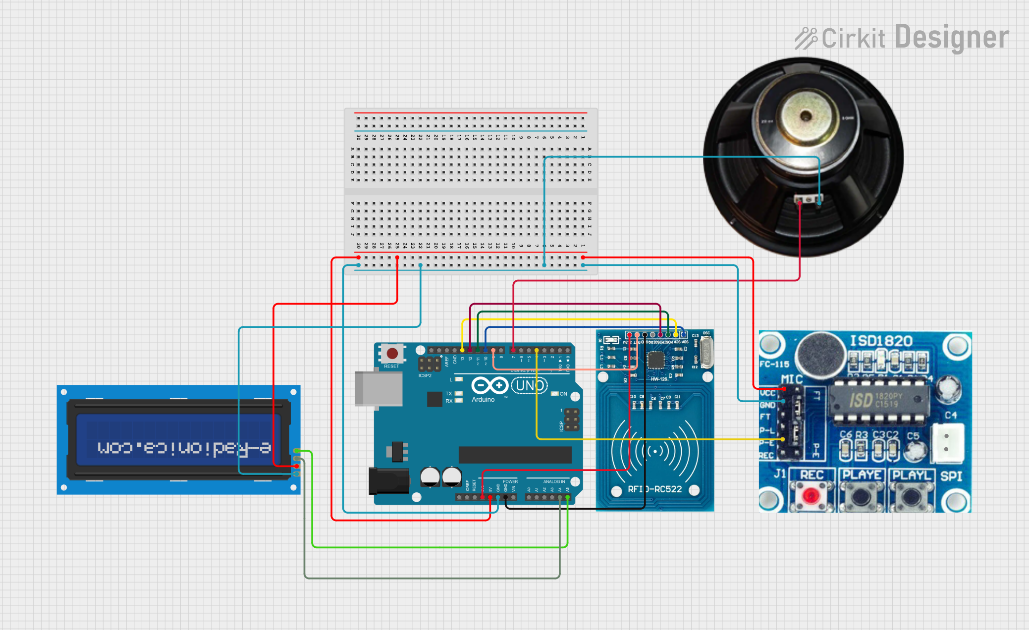
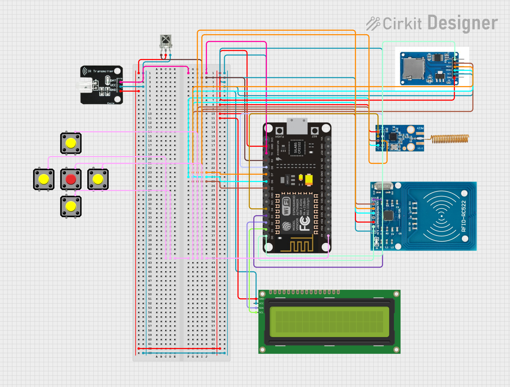
Explore Projects Built with ISD1820
Common Applications
- Voice reminders and alarms
- Interactive toys and games
- Educational tools and learning aids
- Simple audio playback systems
- Prototyping and DIY electronics projects
Technical Specifications
The ISD1820 is a versatile IC with the following key technical details:
| Parameter | Value |
|---|---|
| Operating Voltage | 2.4V to 5.5V |
| Typical Operating Current | 25mA (during playback/recording) |
| Standby Current | <1µA |
| Recording Duration | 8 to 20 seconds (adjustable) |
| Audio Output Power | 0.5W (with 8Ω speaker, 5V supply) |
| Input Signal Type | Microphone (electret condenser) |
| Storage Type | Non-volatile (retains data after power-off) |
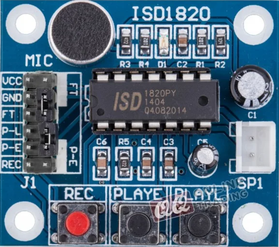
Pin Configuration and Descriptions
The ISD1820 IC has an 8-pin configuration, as detailed below:
| Pin | Name | Description |
|---|---|---|
| 1 | VCC | Power supply input (2.4V to 5.5V). |
| 2 | REC | Active-high input for recording. Pull high to start recording. |
| 3 | PLAYE | Edge-triggered playback input. A high-to-low transition starts playback. |
| 4 | PLAYL | Level-triggered playback input. Hold high to play the recorded message. |
| 5 | FT | Feed-through mode. Pull high to pass microphone input directly to the speaker. |
| 6 | GND | Ground connection. |
| 7 | SP+ | Positive terminal for the speaker output. |
| 8 | SP- | Negative terminal for the speaker output. |
Usage Instructions
How to Use the ISD1820 in a Circuit
- Power Supply: Connect the VCC pin to a 3.3V or 5V power source and the GND pin to ground.
- Microphone Connection: Use an electret condenser microphone for audio input. Connect it to the onboard microphone input (if using a module) or directly to the IC with appropriate biasing.
- Speaker Connection: Attach an 8Ω speaker to the SP+ and SP- pins for audio output.
- Recording: Pull the REC pin high to start recording. Release it to stop recording.
- Playback:
- Use the PLAYE pin for edge-triggered playback (a single pulse starts playback).
- Use the PLAYL pin for level-triggered playback (hold high to play, release to stop).
- Feed-Through Mode: Pull the FT pin high to pass the microphone input directly to the speaker for real-time audio monitoring.
Important Considerations and Best Practices
- Power Supply: Ensure a stable power supply to avoid noise or distortion during recording and playback.
- Recording Duration: Adjust the recording duration by changing the resistor connected to the oscillator pin (if using a standalone IC).
- Speaker Selection: Use an 8Ω speaker for optimal performance. Higher impedance speakers may reduce output volume.
- Microphone Placement: Place the microphone away from the speaker to minimize feedback or echo.
- Triggering: Use debounced switches or microcontroller GPIO pins to trigger the REC, PLAYE, and PLAYL inputs.
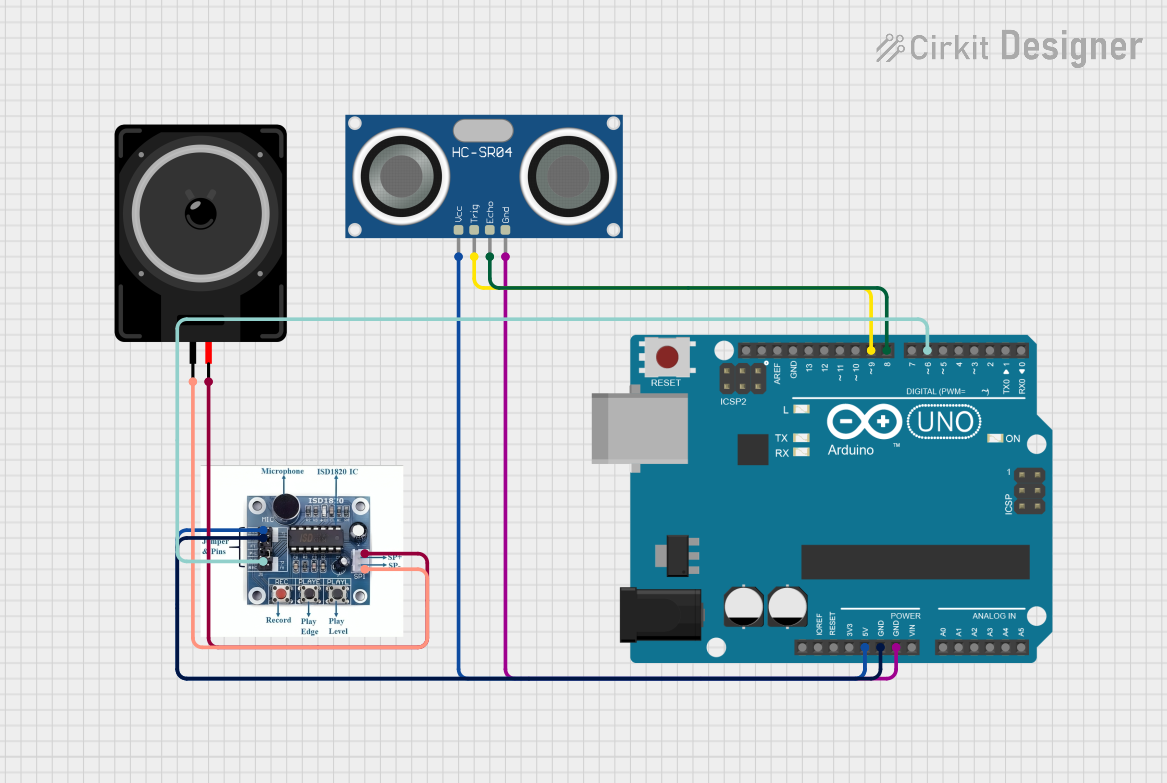
Example: Connecting ISD1820 to Arduino UNO
The ISD1820 can be easily interfaced with an Arduino UNO for automated control. Below is an example code to record and play audio using the ISD1820:
// Pin definitions for ISD1820 connections
const int REC_PIN = 7;    // Connect to REC pin of ISD1820
const int PLAYE_PIN = 8;  // Connect to PLAYE pin of ISD1820
const int PLAYL_PIN = 9;  // Connect to PLAYL pin of ISD1820

void setup() {
  // Set pin modes
  pinMode(REC_PIN, OUTPUT);
  pinMode(PLAYE_PIN, OUTPUT);
  pinMode(PLAYL_PIN, OUTPUT);

  // Initialize all control pins to LOW
  digitalWrite(REC_PIN, LOW);
  digitalWrite(PLAYE_PIN, LOW);
  digitalWrite(PLAYL_PIN, LOW);
}

void loop() {
  // Example: Record audio for 5 seconds
  digitalWrite(REC_PIN, HIGH);  // Start recording
  delay(5000);                  // Record for 5 seconds
  digitalWrite(REC_PIN, LOW);   // Stop recording
  delay(2000);                  // Wait for 2 seconds

  // Example: Play the recorded audio
  digitalWrite(PLAYE_PIN, HIGH);  // Trigger playback
  delay(100);                     // Short delay for edge trigger
  digitalWrite(PLAYE_PIN, LOW);   // Stop playback trigger
  delay(5000);                    // Wait for playback to finish
}
Troubleshooting and FAQs
Common Issues and Solutions
No Sound During Playback:
- Ensure the speaker is properly connected to the SP+ and SP- pins.
- Verify that the recording process was successful (check REC pin operation).
- Check the power supply voltage (should be between 2.4V and 5.5V).
Distorted Audio:
- Use a stable power supply to minimize noise.
- Ensure the microphone is not too close to the speaker to avoid feedback.
- Verify that the speaker impedance is 8Ω.
Recording Does Not Start:
- Confirm that the REC pin is being pulled high during recording.
- Check for loose connections or faulty switches.
Playback Stops Prematurely:
- Ensure the PLAYE or PLAYL pin is triggered correctly.
- Verify that the recorded message duration matches the expected length.
FAQs
Q1: Can the ISD1820 retain recordings after power is turned off?
Yes, the ISD1820 uses non-volatile memory to store recordings, so the audio message is retained even when power is removed.
Q2: How can I extend the recording duration?
The recording duration can be adjusted by changing the external resistor connected to the oscillator pin. Refer to the datasheet for specific resistor values and durations.
Q3: Can I use the ISD1820 with a different speaker impedance?
While an 8Ω speaker is recommended, you can use higher impedance speakers, but the output volume may decrease.
Q4: Is it possible to record and play audio simultaneously?
No, the ISD1820 does not support simultaneous recording and playback.