
How to Use PCA9658: Examples, Pinouts, and Specs
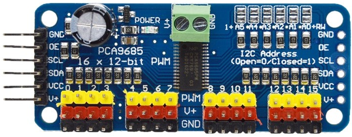
 Design with PCA9658 in Cirkit Designer
Introduction
The PCA9658 is an I2C-bus I/O port expander with interrupt capability, designed to increase the number of I/O pins available for microcontrollers. It features 16 General Purpose Input/Output (GPIO) pins, which can be configured as either inputs or outputs. This component is ideal for applications where additional I/O pins are required but the microcontroller has limited GPIO availability. The PCA9658 supports multiple devices on the same I2C bus, making it highly versatile for complex systems.
Explore Projects Built with PCA9658
 Open Project in Cirkit Designer
 Open Project in Cirkit Designer
 Open Project in Cirkit Designer
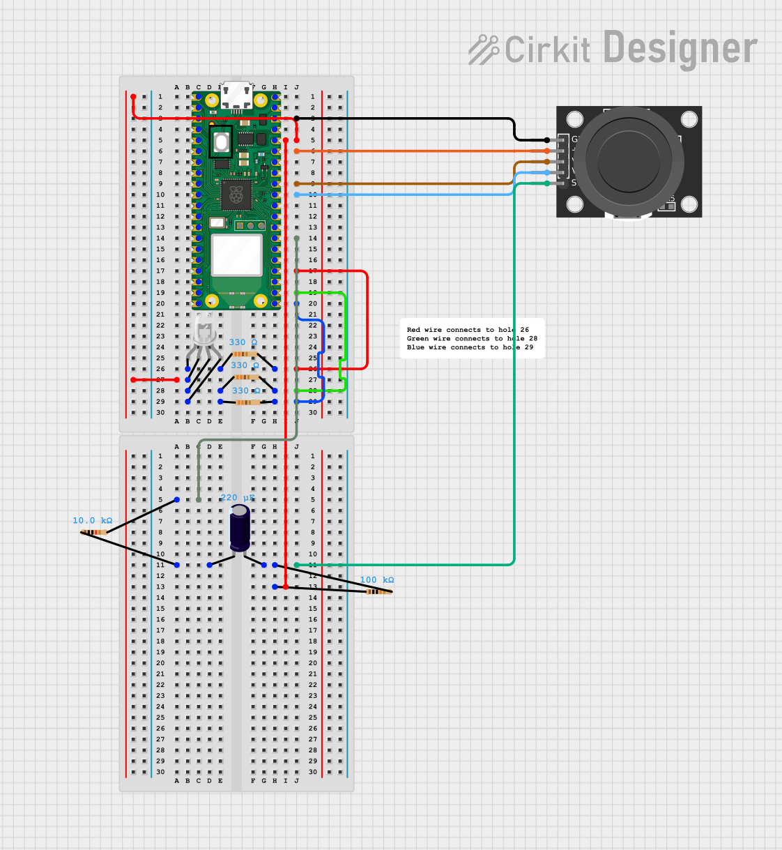 Open Project in Cirkit Designer
Explore Projects Built with PCA9658
Open Project in Cirkit DesignerOpen Project in Cirkit DesignerOpen Project in Cirkit DesignerOpen Project in Cirkit DesignerCommon Applications and Use Cases
- Expanding GPIO capabilities of microcontrollers
- LED control and matrix driving
- Keypad or button matrix interfacing
- Sensor data collection
- Industrial automation systems
- Home automation and IoT devices
Technical Specifications
The PCA9658 is a robust and flexible I/O expander with the following key specifications:
| Parameter | Value |
|---|---|
| Operating Voltage Range | 2.3V to 5.5V |
| I2C Bus Speed | Up to 1 MHz (Fast-mode Plus) |
| GPIO Pins | 16 (configurable as input/output) |
| Interrupt Output | Open-drain, active low |
| Maximum Sink Current (per pin) | 25 mA |
| Maximum Source Current (per pin) | 10 mA |
| Operating Temperature Range | -40°C to +85°C |
| Package Type | TSSOP24, HVQFN24 |
Pin Configuration and Descriptions
The PCA9658 has 24 pins, with the following configuration:
| Pin Number | Pin Name | Description |
|---|---|---|
| 1 | A0 | I2C Address Selection Pin |
| 2 | A1 | I2C Address Selection Pin |
| 3 | A2 | I2C Address Selection Pin |
| 4 | RESET | Active-low Reset Input |
| 5 | INT | Interrupt Output (open-drain, active low) |
| 6-13 | P0.0 - P0.7 | GPIO Port 0 Pins |
| 14-21 | P1.0 - P1.7 | GPIO Port 1 Pins |
| 22 | SDA | I2C Data Line |
| 23 | SCL | I2C Clock Line |
| 24 | VDD | Power Supply (2.3V to 5.5V) |
| - | GND | Ground (connected to the thermal pad) |
Usage Instructions
How to Use the PCA9658 in a Circuit
- Power Supply: Connect the VDD pin to a power source within the operating voltage range (2.3V to 5.5V) and the GND pin to ground.
- I2C Address Configuration: Use the A0, A1, and A2 pins to set the I2C address. These pins can be connected to VDD or GND to configure the address, allowing up to 8 devices on the same I2C bus.
- I2C Communication: Connect the SDA and SCL pins to the corresponding I2C lines of the microcontroller. Use pull-up resistors (typically 4.7kΩ) on these lines.
- GPIO Configuration: Configure the GPIO pins (P0.0 to P1.7) as inputs or outputs by writing to the appropriate control registers via I2C commands.
- Interrupt Handling: If using the interrupt feature, connect the INT pin to an interrupt-capable pin on the microcontroller. The INT pin will go low when a change is detected on any input pin.
Important Considerations and Best Practices
- Use decoupling capacitors (e.g., 0.1 µF) near the VDD pin to stabilize the power supply.
- Avoid exceeding the maximum current ratings for GPIO pins to prevent damage.
- Ensure proper pull-up resistors are used on the I2C lines for reliable communication.
- If unused, tie the RESET pin to VDD to prevent accidental resets.
- When configuring GPIO pins as inputs, consider using external pull-up or pull-down resistors if required by your application.
Example Code for Arduino UNO
Below is an example of how to use the PCA9658 with an Arduino UNO to toggle an LED connected to one of the GPIO pins:
#include <Wire.h> // Include the Wire library for I2C communication

#define PCA9658_ADDR 0x20 // Default I2C address of PCA9658 (A0, A1, A2 = GND)

void setup() {
  Wire.begin(); // Initialize I2C communication
  Serial.begin(9600); // Initialize serial communication for debugging

  // Configure all GPIO pins as outputs
  Wire.beginTransmission(PCA9658_ADDR);
  Wire.write(0x06); // IODIR0 register (Port 0 direction)
  Wire.write(0x00); // Set all pins on Port 0 as outputs
  Wire.endTransmission();

  Wire.beginTransmission(PCA9658_ADDR);
  Wire.write(0x07); // IODIR1 register (Port 1 direction)
  Wire.write(0x00); // Set all pins on Port 1 as outputs
  Wire.endTransmission();
}

void loop() {
  // Turn on an LED connected to P0.0
  Wire.beginTransmission(PCA9658_ADDR);
  Wire.write(0x02); // GPIO0 register (Port 0 output state)
  Wire.write(0x01); // Set P0.0 high
  Wire.endTransmission();
  delay(1000); // Wait for 1 second

  // Turn off the LED
  Wire.beginTransmission(PCA9658_ADDR);
  Wire.write(0x02); // GPIO0 register (Port 0 output state)
  Wire.write(0x00); // Set P0.0 low
  Wire.endTransmission();
  delay(1000); // Wait for 1 second
}
Troubleshooting and FAQs
Common Issues and Solutions
I2C Communication Failure:
- Ensure the SDA and SCL lines have proper pull-up resistors (typically 4.7kΩ).
- Verify the I2C address matches the configuration of the A0, A1, and A2 pins.
- Check for loose or incorrect wiring.
GPIO Pins Not Responding:
- Confirm the GPIO pins are correctly configured as inputs or outputs.
- Ensure the power supply voltage is within the specified range.
Interrupt Pin Not Functioning:
- Verify the INT pin is connected to an interrupt-capable pin on the microcontroller.
- Check if the interrupt feature is enabled in the control registers.
FAQs
Q: Can I use multiple PCA9658 devices on the same I2C bus?
A: Yes, up to 8 devices can be used by configuring the A0, A1, and A2 pins to set unique I2C addresses.
Q: What happens if the RESET pin is left floating?
A: The RESET pin should not be left floating. Tie it to VDD if not used to prevent accidental resets.
Q: Can the PCA9658 drive high-current loads directly?
A: No, the maximum sink current per pin is 25 mA, and the source current is 10 mA. Use external drivers for high-current loads.