How to Use pt 2272 decoder: Examples, Pinouts, and Specs
Introduction
The PT 2272 is a low-power CMOS decoder IC designed for remote control applications. Manufactured by PT, this component is typically paired with the PT 2262 encoder to form a complete wireless communication system. The PT 2272 decodes the encoded signals transmitted by the PT 2262 and outputs the corresponding data, making it ideal for controlling devices such as garage doors, alarms, home automation systems, and other wireless remote-controlled devices.
Explore Projects Built with pt 2272 decoder

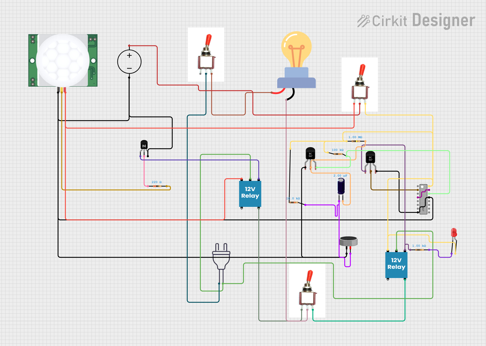

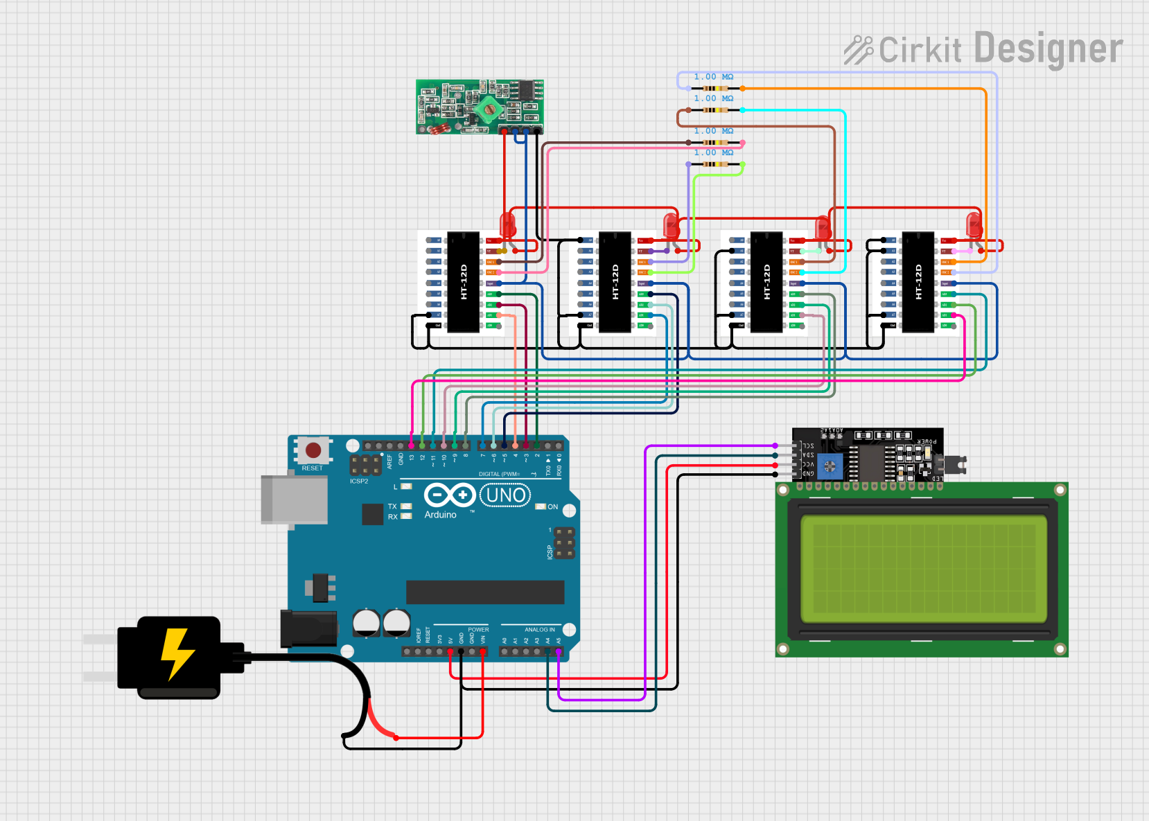
Explore Projects Built with pt 2272 decoder
Common Applications
- Wireless remote control systems
- Garage door openers
- Security alarms
- Home automation
- Remote-controlled toys
Technical Specifications
The PT 2272 is available in multiple configurations, depending on the number of data output pins and the operating mode. Below are the key technical details:
General Specifications
- Operating Voltage: 4.5V to 5.5V
- Operating Current: 4mA (typical)
- Operating Frequency: 315 MHz or 433 MHz (depending on the paired encoder)
- Decoding Capability: 12-bit tri-state address pins
- Output Type: Latch or momentary (depending on the model)
- Operating Temperature: -10°C to +60°C
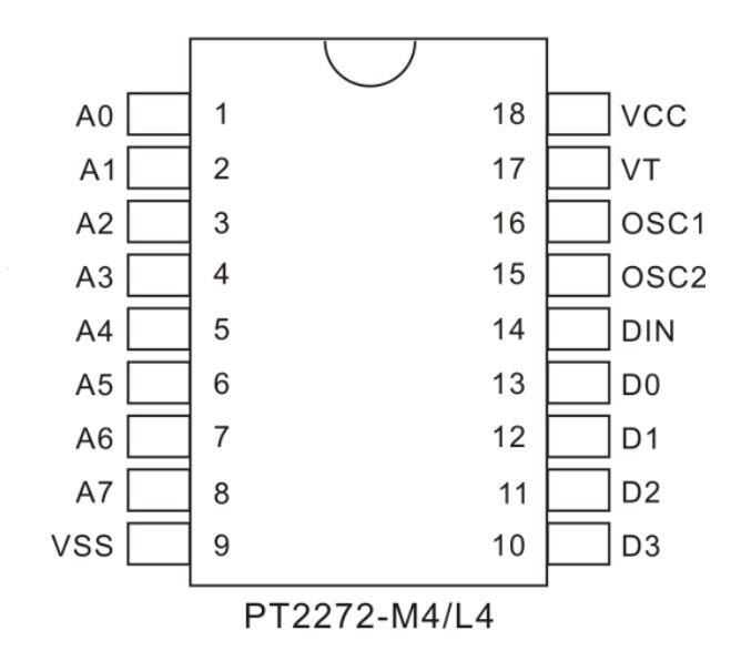
Pin Configuration and Descriptions
The PT 2272 is available in DIP-18 and DIP-20 packages. Below is the pin configuration for the DIP-18 package:
| Pin Number | Pin Name | Description |
|---|---|---|
| 1-6 | A0-A5 | Address input pins (tri-state: high, low, or floating) |
| 7 | VSS | Ground (0V) |
| 8-11 | D0-D3 | Data output pins (decoded signal output) |
| 12 | VT | Valid transmission indicator (high when a valid signal is received) |
| 13-18 | A6-A11 | Address input pins (tri-state: high, low, or floating) |
For the DIP-20 package, additional data output pins (D4-D5) are available, depending on the specific model.
Usage Instructions
How to Use the PT 2272 in a Circuit
Address Configuration:
- Set the address pins (A0-A11) to match the address configuration of the paired PT 2262 encoder.
- Each address pin can be set to high (connected to VCC), low (connected to GND), or left floating.
- Ensure the encoder and decoder have the same address settings for proper communication.
Power Supply:
- Connect the VCC pin to a 5V DC power source and the VSS pin to ground.
Data Outputs:
- The data output pins (D0-D3) will reflect the state of the corresponding data inputs on the PT 2262 encoder.
- Use these outputs to control external devices such as relays, LEDs, or motors.
Valid Transmission (VT) Pin:
- Monitor the VT pin to check if a valid signal is being received. The VT pin goes high when the decoder successfully receives and decodes a signal.
Important Considerations
- Frequency Matching: Ensure the PT 2272 and PT 2262 are operating at the same frequency (e.g., 315 MHz or 433 MHz).
- Noise Filtering: Use decoupling capacitors (e.g., 0.1 µF) near the power supply pins to reduce noise and improve stability.
- Output Driving Capability: The data output pins can only source or sink a limited amount of current. Use external transistors or relays to drive high-power loads.
Example: Connecting PT 2272 to an Arduino UNO
The PT 2272 can be interfaced with an Arduino UNO to read the decoded data and control devices. Below is an example code snippet:
// PT 2272 Decoder with Arduino UNO
// Connect D0-D3 of PT 2272 to Arduino digital pins 2-5
// Connect VT pin of PT 2272 to Arduino digital pin 6

#define VT_PIN 6  // Valid Transmission pin
#define D0_PIN 2  // Data output pin D0
#define D1_PIN 3  // Data output pin D1
#define D2_PIN 4  // Data output pin D2
#define D3_PIN 5  // Data output pin D3

void setup() {
  pinMode(VT_PIN, INPUT);  // Set VT pin as input
  pinMode(D0_PIN, INPUT);  // Set D0 pin as input
  pinMode(D1_PIN, INPUT);  // Set D1 pin as input
  pinMode(D2_PIN, INPUT);  // Set D2 pin as input
  pinMode(D3_PIN, INPUT);  // Set D3 pin as input

  Serial.begin(9600);  // Initialize serial communication
}

void loop() {
  if (digitalRead(VT_PIN) == HIGH) {  // Check if a valid signal is received
    // Read data output pins
    int d0 = digitalRead(D0_PIN);
    int d1 = digitalRead(D1_PIN);
    int d2 = digitalRead(D2_PIN);
    int d3 = digitalRead(D3_PIN);

    // Print the decoded data to the Serial Monitor
    Serial.print("Data: ");
    Serial.print(d0);
    Serial.print(d1);
    Serial.print(d2);
    Serial.println(d3);
  }
}
Troubleshooting and FAQs
Common Issues
No Output on Data Pins:
- Ensure the address pins of the PT 2272 match the address configuration of the PT 2262 encoder.
- Verify that the VT pin goes high when a signal is transmitted.
Interference or Noise:
- Use decoupling capacitors near the power supply pins to filter out noise.
- Ensure the operating frequency is free from interference from other devices.
Invalid Signal Reception:
- Check that the PT 2272 and PT 2262 are operating at the same frequency (e.g., 315 MHz or 433 MHz).
- Verify that the transmitter and receiver are within the specified range.
FAQs
Q: Can the PT 2272 drive high-power devices directly?
A: No, the data output pins of the PT 2272 can only source or sink a small amount of current. Use external transistors, relays, or motor drivers to control high-power devices.
Q: What is the maximum range of the PT 2272 and PT 2262 system?
A: The range depends on the transmitter power and environmental conditions. Typically, it ranges from 50 to 100 meters in open spaces.
Q: Can I use the PT 2272 with other encoders?
A: The PT 2272 is specifically designed to work with the PT 2262 encoder. Using it with other encoders may not yield reliable results.