How to Use Light sensor: Examples, Pinouts, and Specs
Introduction
A light sensor is a device that detects light levels and converts them into an electrical signal. It is commonly used in applications such as automatic lighting systems, environmental monitoring, and consumer electronics. Light sensors are essential for systems that need to respond to changes in ambient light, such as adjusting screen brightness or activating streetlights at dusk.
Explore Projects Built with Light sensor


Explore Projects Built with Light sensor
Technical Specifications
Below are the general technical specifications for a typical light sensor (e.g., an LDR or photodiode-based sensor):
- Operating Voltage: 3.3V to 5V
- Output Type: Analog or Digital (depending on the sensor type)
- Light Sensitivity Range: 0 to 100,000 lux (varies by model)
- Response Time: Typically in milliseconds
- Operating Temperature: -40°C to 85°C
- Power Consumption: Low (typically in the range of microamps to milliamps)
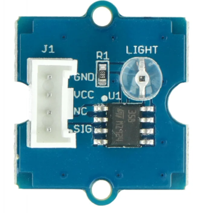
Pin Configuration and Descriptions
The pin configuration for a basic light sensor module (e.g., an LDR module) is as follows:
| Pin Name | Description |
|---|---|
| VCC | Power supply pin (3.3V or 5V, depending on the module). |
| GND | Ground pin for the module. |
| OUT | Output pin that provides an analog or digital signal based on light intensity. |
For more advanced light sensors (e.g., TSL2561 or BH1750), additional pins such as I2C communication lines (SCL and SDA) may be present.
Usage Instructions
How to Use the Component in a Circuit
- Connect the Power Supply:
- Connect the VCC pin to a 3.3V or 5V power source, depending on the sensor's specifications.
- Connect the GND pin to the ground of the circuit.
- Connect the Output Pin:
- For analog sensors, connect the OUT pin to an analog input pin on your microcontroller.
- For digital sensors, connect the OUT pin to a digital input pin or use I2C/SPI communication lines if applicable.
- Place the Sensor Properly:
- Ensure the sensor is exposed to the light source you want to measure.
- Avoid placing the sensor in areas with obstructions or reflective surfaces that may affect accuracy.
Important Considerations and Best Practices
- Calibration: Some light sensors may require calibration to ensure accurate readings in specific environments.
- Avoid Overexposure: Prolonged exposure to intense light sources may degrade the sensor's performance over time.
- Use Pull-Up Resistors: For digital sensors, ensure proper pull-up resistors are used if required by the communication protocol.
- Shielding: If the sensor is used in an environment with electrical noise, consider shielding the sensor and its connections.
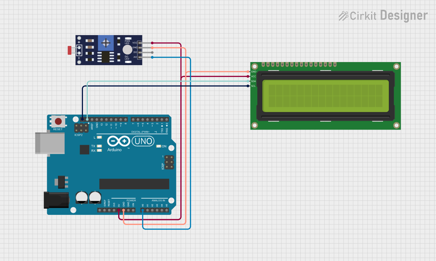
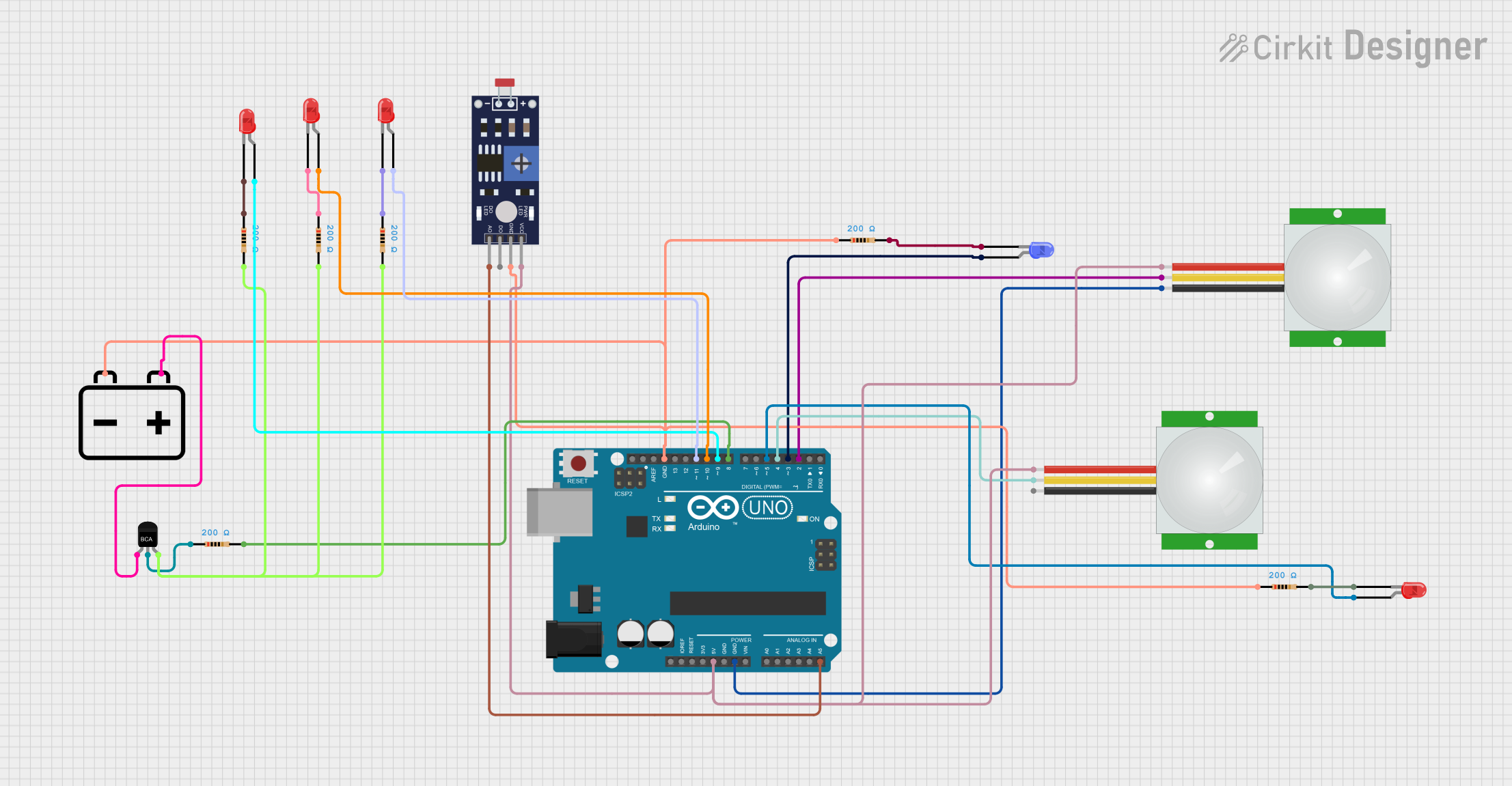
Example: Using a Light Sensor with Arduino UNO
Below is an example of how to use an LDR-based light sensor with an Arduino UNO to read and display light intensity:
// Define the analog pin connected to the light sensor
const int lightSensorPin = A0; // A0 is the analog input pin

void setup() {
  Serial.begin(9600); // Initialize serial communication at 9600 baud
}

void loop() {
  int sensorValue = analogRead(lightSensorPin);
  // Read the analog value from the light sensor

  float voltage = sensorValue * (5.0 / 1023.0);
  // Convert the analog value to voltage (assuming 5V reference)

  Serial.print("Light Sensor Value: ");
  Serial.print(sensorValue); // Print the raw sensor value
  Serial.print(" | Voltage: ");
  Serial.print(voltage); // Print the calculated voltage
  Serial.println(" V");

  delay(500); // Wait for 500ms before the next reading
}
Troubleshooting and FAQs
Common Issues Users Might Face
No Output or Incorrect Readings:
- Cause: Incorrect wiring or loose connections.
- Solution: Double-check the wiring and ensure all connections are secure.
Fluctuating Readings:
- Cause: Electrical noise or unstable power supply.
- Solution: Use decoupling capacitors near the sensor's power pins and ensure a stable power source.
Sensor Not Responding to Light Changes:
- Cause: Sensor placement or damage.
- Solution: Ensure the sensor is not obstructed and is placed in the correct orientation. Replace the sensor if damaged.
Output Saturation:
- Cause: Extremely bright light source.
- Solution: Use a sensor with a higher lux range or add a neutral density filter to reduce light intensity.
FAQs
Q1: Can I use a light sensor outdoors?
A1: Yes, but ensure the sensor is rated for outdoor use and protected from environmental factors like rain and dust.
Q2: How do I increase the sensitivity of my light sensor?
A2: You can adjust the circuit design (e.g., using a different resistor value for an LDR) or use a more sensitive sensor model.
Q3: Can I measure light color with a basic light sensor?
A3: No, basic light sensors only measure intensity. Use a color sensor (e.g., TCS34725) for color detection.
Q4: What is the difference between analog and digital light sensors?
A4: Analog sensors provide a continuous voltage output proportional to light intensity, while digital sensors provide discrete signals or use communication protocols like I2C for data transmission.