How to Use microbit: Examples, Pinouts, and Specs
Introduction
The micro:bit is a small, programmable computer developed by the BBC and manufactured by micro:bit. It is designed to make learning coding and electronics accessible and engaging, especially for students and hobbyists. The micro:bit features a 5x5 LED matrix, two programmable buttons, an accelerometer, a magnetometer, and Bluetooth connectivity. It also includes GPIO pins for connecting external components, making it a versatile tool for a wide range of projects.
Explore Projects Built with microbit


Explore Projects Built with microbit
Common Applications and Use Cases
- Educational Projects: Teaching programming and electronics in schools.
- Prototyping: Rapid development of interactive projects.
- Wearable Technology: Creating wearable devices with sensors and LEDs.
- IoT Projects: Building Bluetooth-enabled devices for the Internet of Things.
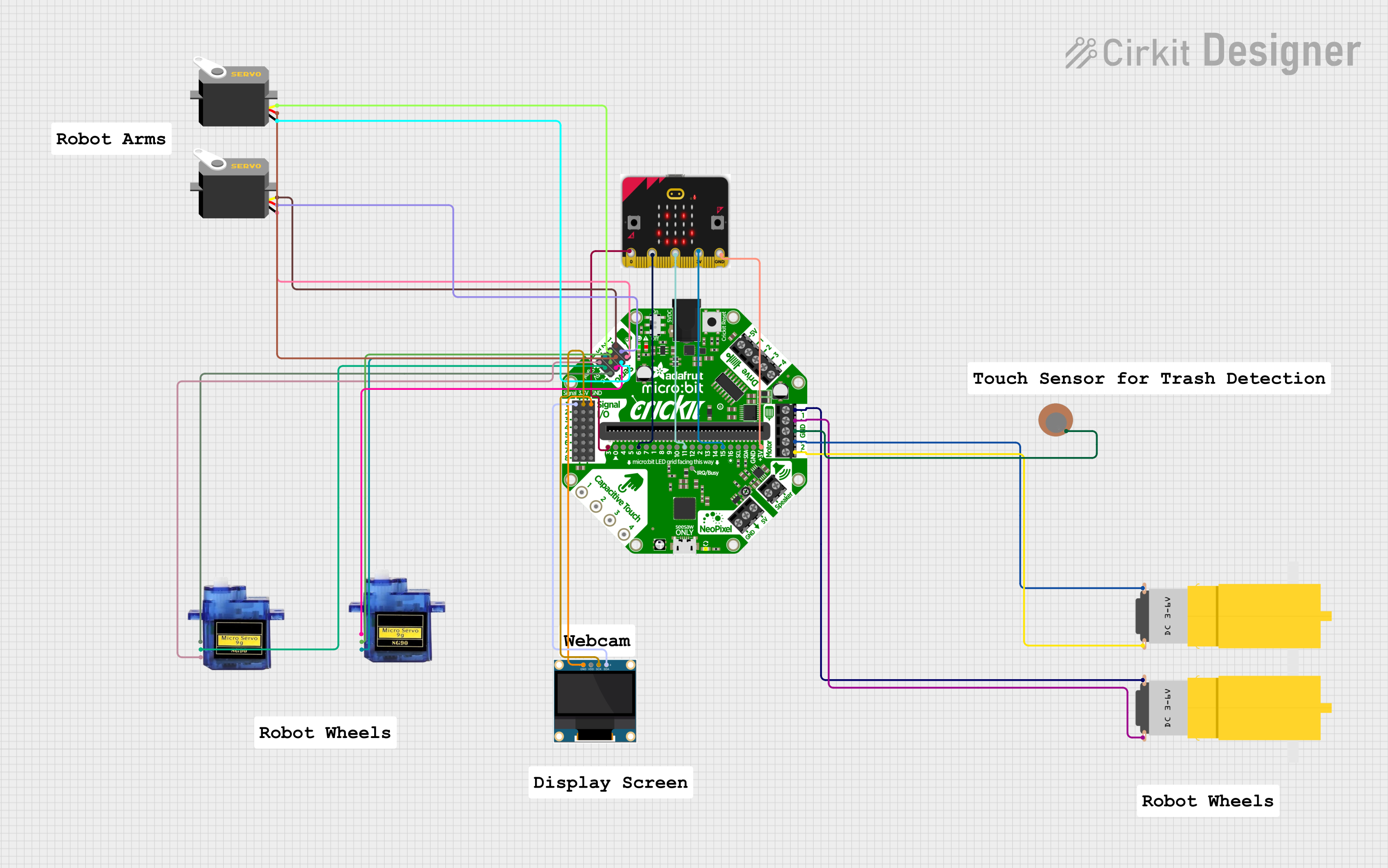
- Robotics: Controlling motors and sensors in robotic systems.
Technical Specifications
The micro:bit is packed with features that make it a powerful yet beginner-friendly device. Below are its key technical details:
Key Technical Details
- Processor: Nordic nRF52833 (ARM Cortex-M4, 64 MHz)
- Memory: 512 KB Flash, 128 KB RAM
- Power Supply: 3V to 3.3V (via USB or battery pack)
- Connectivity: Bluetooth Low Energy (BLE)
- Sensors:
- Accelerometer
- Magnetometer (compass)
- Display: 5x5 LED matrix
- Input: 2 programmable buttons
- GPIO Pins: 25 edge connector pins (3V logic level)
- Dimensions: 52mm x 43mm x 11.7mm
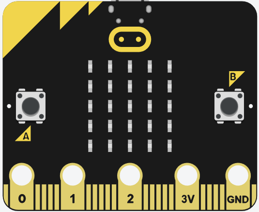
Pin Configuration and Descriptions
The micro:bit has a 25-pin edge connector, with specific pins designated for power, GPIO, and communication. Below is a summary of the pin configuration:
| Pin Number | Name | Description |
|---|---|---|
| 1 | 3V | 3V power output for external components. |
| 2 | GND | Ground connection. |
| 3 | P0 | General-purpose I/O pin (can also be used as an analog input). |
| 4 | P1 | General-purpose I/O pin (can also be used as an analog input). |
| 5 | P2 | General-purpose I/O pin (can also be used as an analog input). |
| 6 | P3 (SDA) | I2C data line (shared with GPIO). |
| 7 | P4 (SCL) | I2C clock line (shared with GPIO). |
| 8 | P5 | Button A input (can also be used as GPIO). |
| 9 | P6 | General-purpose I/O pin. |
| 10 | P7 | General-purpose I/O pin. |
| 11 | P8 | General-purpose I/O pin. |
| 12 | P9 | General-purpose I/O pin. |
| 13 | P10 | General-purpose I/O pin (can also be used as an analog input). |
| 14 | P11 | Button B input (can also be used as GPIO). |
| 15 | P12 | General-purpose I/O pin. |
| 16 | P13 | SPI clock (SCK) or GPIO. |
| 17 | P14 | SPI MISO or GPIO. |
| 18 | P15 | SPI MOSI or GPIO. |
| 19 | P16 | General-purpose I/O pin. |
| 20 | P19 | I2C data line (alternative pin). |
| 21 | P20 | I2C clock line (alternative pin). |
Usage Instructions
The micro:bit is easy to use and program, making it ideal for beginners and advanced users alike. Below are the steps to get started and some best practices for using the micro:bit.
How to Use the micro:bit in a Circuit
- Powering the micro:bit:
- Connect the micro:bit to a computer using a micro-USB cable for power and programming.
- Alternatively, use a battery pack (2x AAA batteries) for portable projects.
- Programming the micro:bit:
- Use the online MakeCode editor (https://makecode.microbit.org) or Python editor (https://python.microbit.org).
- Write your code and download the
.hexfile. - Drag and drop the
.hexfile onto the micro:bit, which appears as a USB drive.
- Connecting External Components:
- Use alligator clips or an edge connector breakout board to connect external components to the GPIO pins.
- Ensure that external components operate within the micro:bit's voltage range (3V to 3.3V).
Important Considerations and Best Practices
- Voltage Levels: The micro:bit operates at 3.3V logic levels. Avoid connecting components that require higher voltages directly to the GPIO pins.
- Current Limitations: The GPIO pins can source/sink a limited amount of current (up to 5mA per pin). Use external transistors or drivers for high-current devices like motors.
- Static Electricity: Handle the micro:bit carefully to avoid damage from static electricity.
- Firmware Updates: Keep the micro:bit firmware updated for compatibility with the latest tools and features.
Example Code for Arduino UNO Integration
The micro:bit can communicate with an Arduino UNO via I2C. Below is an example of how to send data from the micro:bit to the Arduino UNO:
micro:bit Code (MakeCode - JavaScript)
// micro:bit acts as an I2C slave device
let counter = 0
basic.forever(function () {
    pins.i2cWriteNumber(0x08, counter, NumberFormat.UInt8BE)
    counter += 1
    basic.pause(1000) // Send data every second
})
Arduino UNO Code
#include <Wire.h>

void setup() {
  Wire.begin(0x08); // Join I2C bus with address 0x08
  Serial.begin(9600); // Start serial communication for debugging
}

void loop() {
  Wire.requestFrom(0x08, 1); // Request 1 byte from micro:bit
  if (Wire.available()) {
    int data = Wire.read(); // Read the received byte
    Serial.println(data); // Print the data to the Serial Monitor
  }
  delay(1000); // Wait for 1 second before the next request
}
Troubleshooting and FAQs
Common Issues and Solutions
- micro:bit Not Detected by Computer:
- Ensure the USB cable is a data cable (not just a charging cable).
- Try a different USB port or cable.
- Check if the micro:bit's power LED is on.
- Code Not Running on the micro:bit:
- Verify that the
.hexfile was successfully copied to the micro:bit. - Check for syntax errors in the code.
- Reset the micro:bit by pressing the reset button.
- Verify that the
- External Components Not Working:
- Ensure proper connections to the GPIO pins.
- Verify that the components are compatible with the micro:bit's voltage and current limits.
- Bluetooth Not Pairing:
- Ensure the micro:bit is in pairing mode (press and hold the A and B buttons while pressing the reset button).
- Check if the device is discoverable in the Bluetooth settings.
FAQs
- Q: Can I use the micro:bit with other programming languages?
- A: Yes, the micro:bit supports Python, JavaScript, and C++ through various editors.
- Q: How do I update the micro:bit firmware?
- A: Visit https://microbit.org/get-started/user-guide/firmware/ for detailed instructions.
- Q: Can I connect the micro:bit to Wi-Fi?
- A: The micro:bit does not have built-in Wi-Fi, but you can use external Wi-Fi modules like the ESP8266.
By following this documentation, you can unlock the full potential of the micro:bit for your projects!