How to Use ECU: Examples, Pinouts, and Specs
Introduction
An Electronic Control Unit (ECU) is a specialized digital computer designed to manage and control various functions within a vehicle. It plays a critical role in modern automotive systems by processing data from sensors and executing commands to optimize performance, safety, and efficiency. ECUs are commonly used for engine management, transmission control, braking systems, airbag deployment, and more.
Explore Projects Built with ECU

Explore Projects Built with ECU
Common Applications and Use Cases
- Engine Management Systems: Controls fuel injection, ignition timing, and emissions.
- Transmission Control: Manages gear shifting and torque converter operations.
- Anti-lock Braking Systems (ABS): Ensures safe braking by preventing wheel lock-up.
- Airbag Systems: Activates airbags during collisions.
- Advanced Driver Assistance Systems (ADAS): Supports features like lane-keeping assist and adaptive cruise control.
Technical Specifications
Below are the general technical specifications for a typical ECU. Note that specific values may vary depending on the manufacturer and application.
Key Technical Details
- Operating Voltage: 12V DC (typical automotive systems)
- Power Consumption: 5W to 50W (depending on functionality)
- Processor: 16-bit, 32-bit, or 64-bit microcontroller
- Communication Protocols: CAN, LIN, FlexRay, Ethernet
- Operating Temperature Range: -40°C to +125°C
- Memory:
- Flash Memory: 256KB to 4MB
- RAM: 32KB to 512KB
- EEPROM: 8KB to 64KB
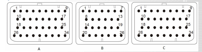
Pin Configuration and Descriptions
The pin configuration of an ECU varies depending on its design and purpose. Below is an example of a generic ECU pinout:
| Pin Number | Pin Name | Description |
|---|---|---|
| 1 | Power Input (VCC) | Connects to the vehicle's 12V power supply. |
| 2 | Ground (GND) | Connects to the vehicle's ground. |
| 3 | CAN_H | High line for CAN bus communication. |
| 4 | CAN_L | Low line for CAN bus communication. |
| 5 | Sensor Input 1 | Analog or digital input from a connected sensor (e.g., temperature sensor). |
| 6 | Sensor Input 2 | Analog or digital input from another sensor (e.g., oxygen sensor). |
| 7 | Actuator Output 1 | Output signal to control an actuator (e.g., fuel injector). |
| 8 | Actuator Output 2 | Output signal to control another actuator (e.g., throttle valve). |
| 9 | Diagnostic Port | Interface for diagnostics and firmware updates (e.g., OBD-II). |
| 10 | PWM Output | Pulse-width modulation output for controlling devices like motors or solenoids. |
Usage Instructions
How to Use the ECU in a Circuit
- Power Supply: Connect the ECU's power input pin to the vehicle's 12V power supply and the ground pin to the vehicle's chassis ground.
- Sensor Connections: Attach the appropriate sensors (e.g., temperature, pressure, or oxygen sensors) to the designated input pins.
- Actuator Connections: Connect actuators (e.g., fuel injectors, throttle valves) to the output pins as specified in the ECU's datasheet.
- Communication: Use the CAN_H and CAN_L pins to integrate the ECU into the vehicle's CAN bus network for data exchange with other ECUs.
- Diagnostics: Connect a diagnostic tool to the diagnostic port for troubleshooting or firmware updates.
Important Considerations and Best Practices
- Voltage Levels: Ensure the ECU operates within its specified voltage range to avoid damage.
- Wiring: Use shielded cables for communication lines (e.g., CAN bus) to minimize electromagnetic interference.
- Grounding: Proper grounding is essential to prevent noise and ensure reliable operation.
- Firmware Updates: Regularly update the ECU firmware to improve performance and address potential bugs.
- Heat Management: Install the ECU in a location with adequate ventilation to prevent overheating.
Example Code for Arduino Integration
While ECUs are typically standalone systems, they can communicate with microcontrollers like Arduino via the CAN bus. Below is an example of how to read data from an ECU using an Arduino UNO and a CAN bus shield.
#include <SPI.h>
#include <mcp_can.h>

// Define the CAN bus shield's CS pin
#define CAN_CS_PIN 10

// Initialize the CAN bus object
MCP_CAN CAN(CAN_CS_PIN);

void setup() {
  Serial.begin(9600); // Start serial communication for debugging

  // Initialize the CAN bus at 500 kbps
  if (CAN.begin(MCP_ANY, 500000, MCP_8MHZ) == CAN_OK) {
    Serial.println("CAN bus initialized successfully!");
  } else {
    Serial.println("Error initializing CAN bus.");
    while (1); // Halt execution if initialization fails
  }

  CAN.setMode(MCP_NORMAL); // Set CAN bus to normal mode
  Serial.println("CAN bus set to normal mode.");
}

void loop() {
  unsigned char len = 0;
  unsigned char buf[8];

  // Check if data is available on the CAN bus
  if (CAN.checkReceive() == CAN_MSGAVAIL) {
    CAN.readMsgBuf(&len, buf); // Read the received message

    // Print the received data
    Serial.print("Received data: ");
    for (int i = 0; i < len; i++) {
      Serial.print(buf[i], HEX);
      Serial.print(" ");
    }
    Serial.println();
  }
}
Note: This example assumes the use of an MCP2515-based CAN bus shield. Ensure the ECU's CAN bus baud rate matches the Arduino's configuration.
Troubleshooting and FAQs
Common Issues
ECU Not Powering On:
- Cause: Incorrect wiring or insufficient power supply.
- Solution: Verify the power and ground connections. Ensure the power supply provides the required voltage and current.
No Communication with Other ECUs:
- Cause: Faulty CAN bus wiring or mismatched baud rates.
- Solution: Check the CAN_H and CAN_L connections. Ensure all devices on the CAN bus use the same baud rate.
Sensors Not Responding:
- Cause: Damaged sensors or incorrect connections.
- Solution: Test the sensors individually and verify their connections to the ECU.
Overheating:
- Cause: Poor ventilation or excessive power consumption.
- Solution: Relocate the ECU to a cooler area or improve airflow around it.
FAQs
Q: Can I use an ECU from one vehicle in another?
- A: It depends on compatibility. ECUs are often programmed for specific vehicles and may require reprogramming to work in a different model.
Q: How do I update the ECU firmware?
- A: Use a diagnostic tool or software provided by the ECU manufacturer. Follow the instructions carefully to avoid bricking the ECU.
Q: What happens if the ECU fails?
- A: A failed ECU can cause various issues, such as engine misfires, poor fuel efficiency, or complete vehicle inoperability. Replace or repair the ECU as needed.
Q: Can I repair a damaged ECU myself?
- A: ECU repair requires specialized tools and expertise. It is recommended to consult a professional technician.