How to Use Antenna GPS Embedded SMA: Examples, Pinouts, and Specs
Introduction
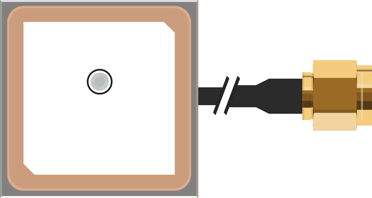
The Antenna GPS Embedded SMA is a compact and high-performance GPS antenna designed for a wide range of applications that require reliable positioning and navigation information. With its SMA connector, it can be easily integrated into various GPS-enabled devices such as vehicle tracking systems, handheld navigation units, and other outdoor positioning gadgets.
Explore Projects Built with Antenna GPS Embedded SMA
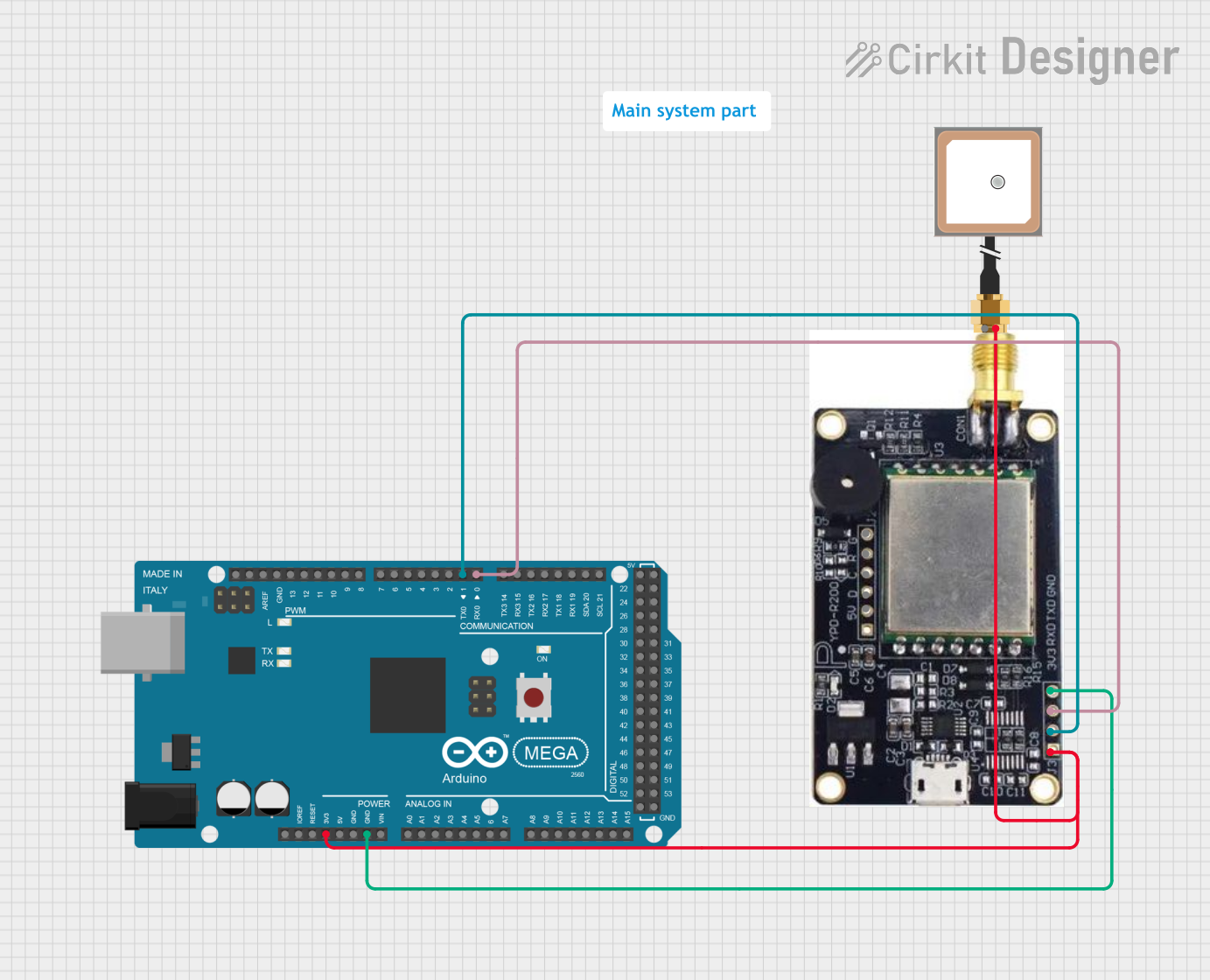
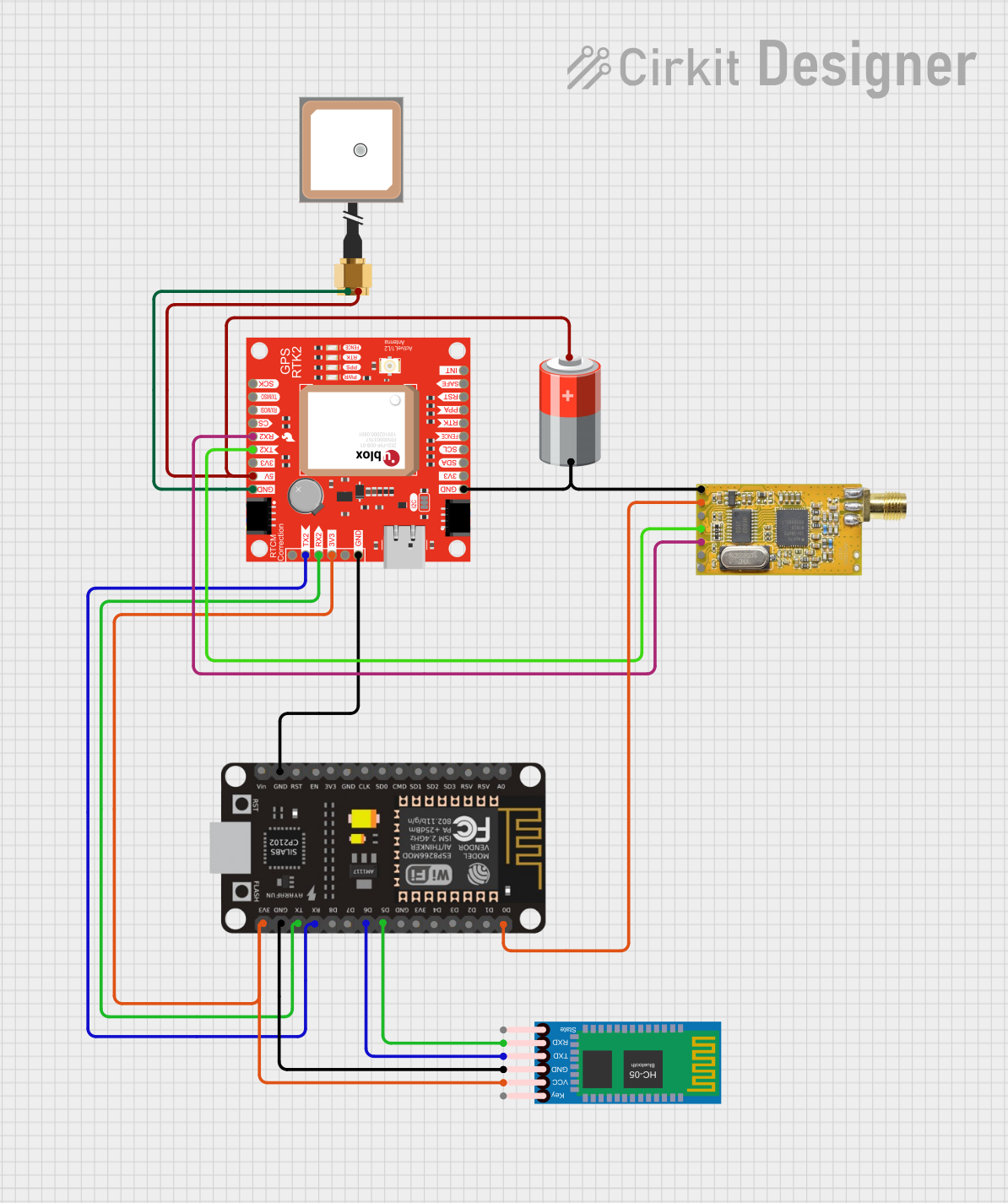


Explore Projects Built with Antenna GPS Embedded SMA
Common Applications and Use Cases
- Vehicle and asset tracking
- Personal navigation devices
- Outdoor sports and recreation
- Emergency location services
- UAVs (Unmanned Aerial Vehicles) and drones
- Marine navigation
Technical Specifications
Key Technical Details
- Frequency Range: 1575.42 MHz (L1 band)
- Impedance: 50 Ohms nominal
- Polarization: RHCP (Right-Hand Circular Polarization)
- Gain: Typically 28 dB
- Voltage: 3V to 5V DC
- Current Consumption: 10mA typical at 3V
- Operating Temperature: -40°C to +85°C
Pin Configuration and Descriptions
| Pin Number | Description | Notes |
|---|---|---|
| 1 | RF Output | Connected to the GPS receiver |
| 2 | Ground | Connect to system ground |
Usage Instructions
Integration into a Circuit
Connection: Connect the RF output of the Antenna GPS Embedded SMA to the antenna input of your GPS receiver module. Ensure that the SMA connector is properly secured to avoid signal loss.
Power Supply: Provide a stable DC voltage between 3V and 5V to the antenna. This can usually be sourced from the GPS module or the main system power supply.
Grounding: Establish a good ground connection to minimize noise and improve signal quality. The ground pin should be connected to the system ground plane.
Important Considerations and Best Practices
- Mounting: For optimal performance, mount the antenna with a clear view of the sky. Avoid obstructions such as tall buildings or heavy foliage.
- Cable Length: Keep the cable between the antenna and GPS receiver as short as possible to reduce signal attenuation.
- Interference: Be aware of potential interference sources such as high-power transmitters or other RF devices. Position the antenna away from these sources if possible.
- Weatherproofing: If the antenna is to be used outdoors, ensure it is housed in a weatherproof enclosure or is itself rated for outdoor use.
Troubleshooting and FAQs
Common Issues
- Poor Signal Quality: Ensure the antenna has a clear view of the sky and is not obstructed. Check for proper grounding and stable power supply.
- No Signal: Verify that all connections are secure. Check the antenna and cable for physical damage. Ensure the GPS receiver is functioning correctly.
Solutions and Tips
- Repositioning: If signal quality is consistently poor, try repositioning the antenna to a different location.
- Cable Check: Inspect the SMA connector and cable for any signs of damage or wear. Replace if necessary.
- Power Supply: Confirm that the voltage supplied to the antenna is within the specified range and is stable.
FAQs
Q: Can I use this antenna with any GPS receiver? A: As long as the receiver supports an SMA connector and the voltage requirements match, this antenna should be compatible.
Q: Does the antenna require an external power source? A: Yes, the antenna needs a DC power supply between 3V and 5V to operate.
Q: What is the maximum cable length I can use with this antenna? A: The maximum cable length depends on the quality of the cable and the specific application. However, it is generally recommended to keep the cable as short as possible to minimize signal loss.
Q: Is this antenna waterproof? A: The datasheet or product specifications should be consulted for environmental ratings. If the antenna is not inherently waterproof, it should be placed in a weatherproof enclosure for outdoor use.
Example Code for Arduino UNO
Below is an example code snippet for initializing a generic GPS module connected to an Arduino UNO. This code assumes the use of a serial GPS module and the TinyGPS++ library for parsing GPS data.
#include <TinyGPS++.h>
#include <SoftwareSerial.h>

// The serial connection to the GPS module
SoftwareSerial gpsSerial(4, 3); // RX, TX

TinyGPSPlus gps;

void setup() {
  Serial.begin(9600);
  gpsSerial.begin(9600);
  Serial.println("GPS Module Test");
}

void loop() {
  // This sketch displays information every time a new sentence is correctly encoded.
  while (gpsSerial.available() > 0) {
    if (gps.encode(gpsSerial.read())) {
      displayInfo();
    }
  }
}

void displayInfo() {
  if (gps.location.isValid()) {
    Serial.print("Latitude: ");
    Serial.println(gps.location.lat(), 6);
    Serial.print("Longitude: ");
    Serial.println(gps.location.lng(), 6);
  } else {
    Serial.println("Location: Not Available");
  }

  Serial.print("Date: ");
  if (gps.date.isValid()) {
    Serial.print(gps.date.month());
    Serial.print("/");
    Serial.print(gps.date.day());
    Serial.print("/");
    Serial.println(gps.date.year());
  } else {
    Serial.println("Not Available");
  }

  Serial.print("Time: ");
  if (gps.time.isValid()) {
    Serial.print(gps.time.hour());
    Serial.print(":");
    Serial.print(gps.time.minute());
    Serial.print(":");
    Serial.println(gps.time.second());
  } else {
    Serial.println("Not Available");
  }

  Serial.println();
  delay(1000);
}
Note: The above code is for demonstration purposes only. Ensure that you have the TinyGPS++ library installed in your Arduino IDE before compiling the code. The GPS module should be connected to the pins defined in the gpsSerial object (pins 4 and 3 in this case). The antenna should be connected to the GPS module as per the module's datasheet.