How to Use GY‑MS5837: Examples, Pinouts, and Specs
Introduction
The GY‑MS5837 is a high-resolution pressure sensor module designed for precise measurement of atmospheric pressure and depth. Manufactured by GY‑MS5837, this sensor features a digital output and is capable of measuring both pressure and temperature. Its compact size and high accuracy make it ideal for a wide range of applications, including weather stations, underwater exploration, and altitude measurement in drones or other devices.
Explore Projects Built with GY‑MS5837


Explore Projects Built with GY‑MS5837
Common Applications
- Weather monitoring systems
- Underwater depth measurement for diving or robotics
- Altitude measurement in drones and aircraft
- Barometric pressure sensing for environmental studies
- Industrial process monitoring
Technical Specifications
The GY‑MS5837 module is based on the MS5837 sensor and provides the following key specifications:
| Parameter | Value |
|---|---|
| Operating Voltage | 3.3V to 5V |
| Pressure Range | 0 to 30 bar (0 to 3000 kPa) |
| Temperature Range | -40°C to +85°C |
| Pressure Resolution | 0.2 mbar |
| Temperature Resolution | 0.01°C |
| Communication Interface | I²C |
| I²C Address | 0x76 (default) |
| Dimensions | 13mm x 10mm x 3mm |
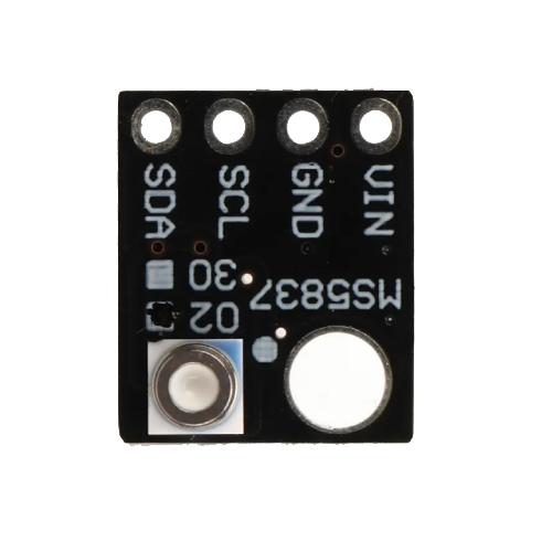
Pin Configuration
The GY‑MS5837 module has a 4-pin interface for easy integration into circuits. The pinout is as follows:
| Pin | Name | Description |
|---|---|---|
| 1 | VCC | Power supply input (3.3V to 5V) |
| 2 | GND | Ground |
| 3 | SCL | I²C clock line |
| 4 | SDA | I²C data line |
Usage Instructions
Connecting the GY‑MS5837 to a Circuit
- Power Supply: Connect the VCC pin to a 3.3V or 5V power source and the GND pin to ground.
- I²C Communication: Connect the SCL and SDA pins to the corresponding I²C pins on your microcontroller (e.g., Arduino UNO).
- Pull-Up Resistors: Ensure that the I²C lines (SCL and SDA) have pull-up resistors (typically 4.7kΩ) if not already present on the module.
Example: Using GY‑MS5837 with Arduino UNO
Below is an example Arduino sketch to read pressure and temperature data from the GY‑MS5837 sensor:
#include <Wire.h>
#include <MS5837.h> // Include the MS5837 library

MS5837 sensor; // Create an instance of the MS5837 class

void setup() {
  Serial.begin(9600); // Initialize serial communication
  Wire.begin();       // Initialize I²C communication

  if (!sensor.init()) {
    // Check if the sensor initializes successfully
    Serial.println("Sensor initialization failed!");
    while (1); // Halt execution if initialization fails
  }

  sensor.setModel(MS5837::MS5837_30BA); // Set the sensor model
  sensor.setFluidDensity(997);         // Set fluid density (997 kg/m³ for water)
}

void loop() {
  sensor.read(); // Read pressure and temperature data

  // Print pressure in mbar
  Serial.print("Pressure (mbar): ");
  Serial.println(sensor.pressure());

  // Print temperature in Celsius
  Serial.print("Temperature (°C): ");
  Serial.println(sensor.temperature());

  delay(1000); // Wait 1 second before the next reading
}
Important Considerations
- Power Supply: Ensure the module is powered within the specified voltage range (3.3V to 5V).
- I²C Address: The default I²C address is 0x76. If multiple devices are connected to the same I²C bus, ensure there are no address conflicts.
- Environmental Conditions: Avoid exposing the sensor to extreme conditions beyond its operating range to prevent damage.
Troubleshooting and FAQs
Common Issues
No Data Output:
- Ensure the sensor is properly connected to the microcontroller.
- Verify that the I²C pull-up resistors are in place.
- Check the I²C address (default is 0x76) and ensure it matches the code.
Incorrect Readings:
- Confirm that the sensor is operating within its specified temperature and pressure range.
- Check for loose or faulty connections in the circuit.
Initialization Fails:
- Ensure the MS5837 library is correctly installed in the Arduino IDE.
- Verify that the sensor is receiving power and that the I²C lines are functioning.
FAQs
Q: Can the GY‑MS5837 be used underwater?
A: Yes, the GY‑MS5837 is designed for underwater applications and can measure depth up to 30 bar (approximately 300 meters underwater).
Q: What is the accuracy of the pressure readings?
A: The sensor provides a pressure resolution of 0.2 mbar, making it highly accurate for most applications.
Q: Can I use the GY‑MS5837 with a 5V microcontroller?
A: Yes, the module supports a power supply range of 3.3V to 5V, making it compatible with both 3.3V and 5V systems.
Q: Do I need to calibrate the sensor?
A: The sensor is factory-calibrated, so no additional calibration is required for standard use. However, you may need to adjust for specific environmental conditions or fluid densities.