How to Use DTMF Encoder: Examples, Pinouts, and Specs
Introduction
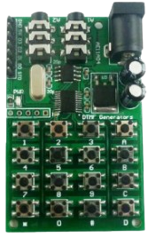
A DTMF (Dual-Tone Multi-Frequency) Encoder is an electronic component that generates specific audio tones corresponding to the keys pressed on a telephone keypad. Each keypress produces a combination of two distinct frequencies, one from a low-frequency group and one from a high-frequency group. These tones are widely used in telecommunication systems for signaling, such as dialing phone numbers or sending commands over audio channels.
Explore Projects Built with DTMF Encoder

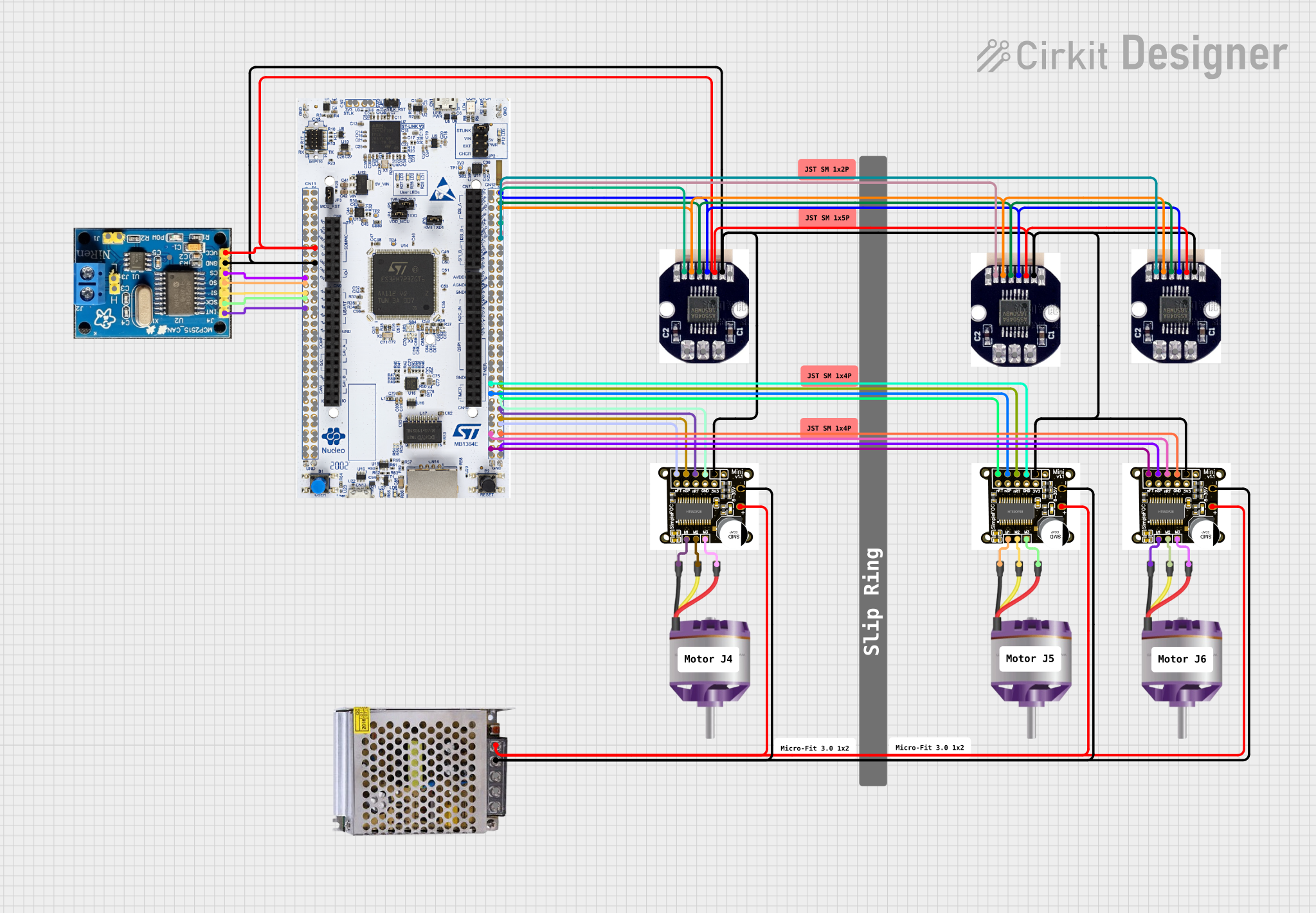

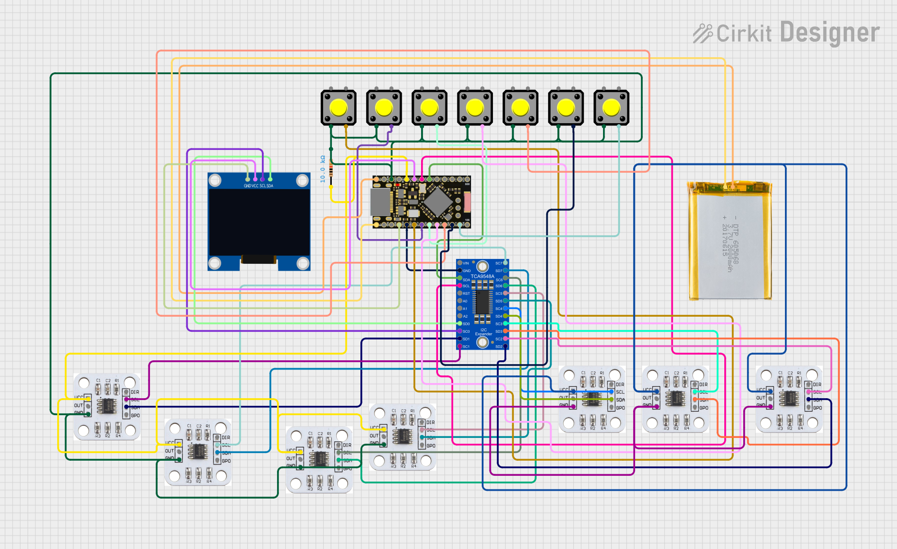
Explore Projects Built with DTMF Encoder
Common Applications and Use Cases
- Telephone systems for dialing and signaling
- Remote control systems using audio tones
- Security systems for access control
- Audio-based data transmission
- Interactive voice response (IVR) systems
Technical Specifications
The following table outlines the key technical details of a typical DTMF Encoder:
| Parameter | Value |
|---|---|
| Operating Voltage | 2.5V to 5.5V |
| Operating Current | 1mA to 3mA |
| Frequency Accuracy | ±1.5% |
| Output Signal | Dual-tone audio signal |
| Operating Temperature | -40°C to +85°C |
| Package Type | DIP, SOIC |
Pin Configuration and Descriptions
Below is the pin configuration for a common DTMF Encoder IC, such as the MT8870 or similar:
| Pin Number | Pin Name | Description |
|---|---|---|
| 1 | VDD | Positive power supply (2.5V to 5.5V). |
| 2 | GND | Ground connection. |
| 3 | IN+ | Non-inverting input for the audio signal. |
| 4 | IN- | Inverting input for the audio signal. |
| 5 | OSC1 | Oscillator input. Connect to a crystal or external clock source. |
| 6 | OSC2 | Oscillator output. Connect to a crystal or leave open if using an external clock. |
| 7 | D0 | Data output bit 0 (LSB). |
| 8 | D1 | Data output bit 1. |
| 9 | D2 | Data output bit 2. |
| 10 | D3 | Data output bit 3 (MSB). |
| 11 | STD | Signal detect output. Indicates valid DTMF signal detection. |
| 12 | OE | Output enable. Active low to enable data outputs. |
| 13 | VREF | Reference voltage output for internal circuitry. |
| 14 | GS | Gain select. Used to adjust input gain. |
Usage Instructions
How to Use the Component in a Circuit
- Power Supply: Connect the VDD pin to a stable power source (2.5V to 5.5V) and the GND pin to ground.
- Oscillator Setup: Connect a crystal oscillator (typically 3.579 MHz) between the OSC1 and OSC2 pins, or provide an external clock signal to OSC1.
- Audio Input: Feed the audio signal to the IN+ and IN- pins. Use a capacitor for AC coupling if necessary.
- Output Enable: Ensure the OE pin is pulled low to enable the data output pins (D0-D3).
- Data Output: Monitor the D0-D3 pins for the decoded DTMF signal. These pins represent a 4-bit binary code corresponding to the detected keypress.
- Signal Detection: Use the STD pin to check if a valid DTMF signal is detected.
Important Considerations and Best Practices
- Use decoupling capacitors (e.g., 0.1 µF) near the VDD pin to reduce noise and ensure stable operation.
- Ensure the input signal level is within the acceptable range for the encoder (typically 0.5V to 1.5V peak-to-peak).
- Avoid excessive noise on the input signal, as it may lead to incorrect tone detection.
- If using the component with a microcontroller, ensure the microcontroller's input pins are compatible with the encoder's output logic levels.
Example: Connecting to an Arduino UNO
Below is an example of interfacing a DTMF Encoder with an Arduino UNO to detect keypresses:
// DTMF Decoder Example with Arduino UNO
// Connect D0-D3 pins of the DTMF Encoder to Arduino digital pins 2-5
// Connect the STD pin to Arduino digital pin 6 for signal detection

#define D0_PIN 2  // DTMF data output bit 0
#define D1_PIN 3  // DTMF data output bit 1
#define D2_PIN 4  // DTMF data output bit 2
#define D3_PIN 5  // DTMF data output bit 3
#define STD_PIN 6 // Signal detect pin

void setup() {
  // Set D0-D3 and STD pins as inputs
  pinMode(D0_PIN, INPUT);
  pinMode(D1_PIN, INPUT);
  pinMode(D2_PIN, INPUT);
  pinMode(D3_PIN, INPUT);
  pinMode(STD_PIN, INPUT);

  // Initialize serial communication for debugging
  Serial.begin(9600);
}

void loop() {
  // Check if a valid DTMF signal is detected
  if (digitalRead(STD_PIN) == HIGH) {
    // Read the 4-bit binary code from D0-D3
    int dtmfCode = (digitalRead(D3_PIN) << 3) |
                   (digitalRead(D2_PIN) << 2) |
                   (digitalRead(D1_PIN) << 1) |
                   digitalRead(D0_PIN);

    // Print the detected DTMF code
    Serial.print("Detected DTMF Code: ");
    Serial.println(dtmfCode, HEX); // Print in hexadecimal format
  }
}
Troubleshooting and FAQs
Common Issues and Solutions
No Output Signal:
- Ensure the power supply is stable and within the specified range.
- Verify the oscillator circuit is correctly configured and functioning.
- Check the input signal level and ensure it is within the acceptable range.
Incorrect Tone Detection:
- Reduce noise on the input signal by using proper shielding and filtering.
- Verify the gain setting (GS pin) is appropriate for the input signal level.
STD Pin Not Activating:
- Ensure the input signal contains valid DTMF tones.
- Check the wiring and connections to the STD pin.
FAQs
Q: Can I use a different crystal frequency for the oscillator?
A: No, the DTMF Encoder is typically designed to work with a 3.579 MHz crystal. Using a different frequency may result in incorrect tone generation.
Q: What is the purpose of the STD pin?
A: The STD (Signal Detect) pin indicates when a valid DTMF signal is detected. It can be used to trigger further processing in your circuit.
Q: Can the DTMF Encoder be used for wireless communication?
A: Yes, the generated tones can be transmitted over audio channels, such as radio or telephone lines, for remote signaling.