How to Use PUSH BUTTON - STOP: Examples, Pinouts, and Specs
Introduction
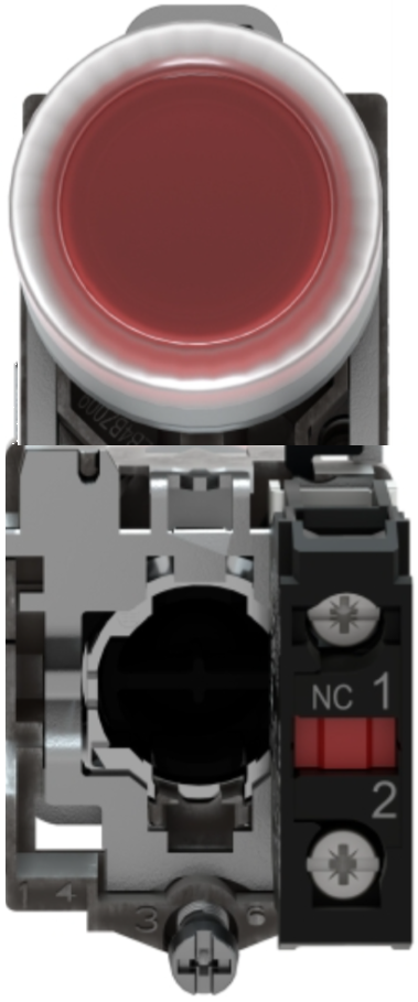
The PUSH BUTTON - STOP (Manufacturer: Schneider, Part ID: XB4-BP42) is a momentary switch designed to interrupt a circuit when pressed. It is commonly used as a safety or emergency stop mechanism in industrial and electronic systems. This component is highly reliable and durable, making it suitable for applications where safety and precision are critical.
Explore Projects Built with PUSH BUTTON - STOP


Explore Projects Built with PUSH BUTTON - STOP
Common Applications and Use Cases
- Emergency stop mechanisms in industrial machinery
- Control panels for automation systems
- Safety circuits in electronic devices
- Robotics and process control systems
- User interfaces for stopping operations in consumer electronics
Technical Specifications
The following table outlines the key technical details of the Schneider XB4-BP42 push button:
| Parameter | Value |
|---|---|
| Manufacturer | Schneider |
| Part ID | XB4-BP42 |
| Type | Momentary Push Button (Stop) |
| Contact Configuration | 1 Normally Closed (1NC) |
| Operating Voltage | 24V to 240V AC/DC |
| Current Rating | 10A @ 240V AC |
| Mechanical Durability | 1,000,000 operations |
| Electrical Durability | 500,000 operations |
| Mounting Type | Panel Mount |
| Actuator Color | Red |
| Actuator Type | Round, Flush |
| Terminal Type | Screw Terminals |
| Operating Temperature | -25°C to +70°C |
| IP Rating | IP66 (Dust-tight, Water-resistant) |
Pin Configuration and Descriptions
The push button has screw terminals for connecting to the circuit. Below is the pin configuration:
| Terminal | Description |
|---|---|
| Terminal 1 | Input connection for the circuit |
| Terminal 2 | Output connection for the circuit |
Usage Instructions
How to Use the Component in a Circuit
Mounting the Push Button:
- Drill a hole in the panel with a diameter of 22mm to fit the push button.
- Secure the push button using the mounting hardware provided.
Wiring the Push Button:
- Connect the input wire to Terminal 1 and the output wire to Terminal 2.
- Ensure the connections are tight and secure to avoid loose contacts.
Integrating into a Circuit:
- Place the push button in series with the load or control circuit.
- When the button is pressed, the circuit will open, interrupting the current flow.
Testing the Circuit:
- After wiring, test the circuit to ensure the push button operates as expected.
- Press the button to verify that it stops the operation or process.
Important Considerations and Best Practices
- Ensure the push button is rated for the voltage and current of your application.
- Use proper insulation and strain relief for the wires to prevent accidental disconnections.
- Avoid exposing the push button to extreme environmental conditions beyond its rated IP66 protection.
- Regularly inspect the push button for wear and tear, especially in high-use applications.
Example: Connecting to an Arduino UNO
The push button can be used with an Arduino UNO for simple stop functionality. Below is an example circuit and code:
Circuit Setup
- Connect Terminal 1 of the push button to a digital input pin (e.g., pin 2) on the Arduino.
- Connect Terminal 2 to the ground (GND) pin of the Arduino.
- Use a pull-up resistor (10kΩ) between the digital input pin and the 5V pin to ensure stable readings.
Arduino Code
// Define the pin connected to the push button
const int buttonPin = 2;

// Variable to store the button state
int buttonState = 0;

void setup() {
  // Set the button pin as input with pull-up resistor
  pinMode(buttonPin, INPUT_PULLUP);

  // Initialize serial communication for debugging
  Serial.begin(9600);
}

void loop() {
  // Read the state of the push button
  buttonState = digitalRead(buttonPin);

  // Check if the button is pressed (LOW state due to pull-up resistor)
  if (buttonState == LOW) {
    Serial.println("Stop button pressed!");
    // Add code here to stop a process or operation
  } else {
    Serial.println("Button not pressed.");
  }

  // Small delay to debounce the button
  delay(50);
}
Troubleshooting and FAQs
Common Issues and Solutions
Push Button Not Stopping the Circuit
- Cause: Loose or incorrect wiring.
- Solution: Double-check the connections to ensure the input and output wires are properly secured to the terminals.
Button Feels Stuck or Hard to Press
- Cause: Dirt or debris in the actuator mechanism.
- Solution: Clean the button with a dry cloth or compressed air. Avoid using liquids.
Intermittent Operation
- Cause: Worn-out contacts or improper mounting.
- Solution: Inspect the contacts for wear and replace the push button if necessary. Ensure the button is securely mounted.
Arduino Not Detecting Button Press
- Cause: Missing pull-up resistor or incorrect pin configuration.
- Solution: Use a pull-up resistor or enable the internal pull-up resistor in the Arduino code.
FAQs
Q1: Can this push button be used outdoors?
A1: Yes, the XB4-BP42 has an IP66 rating, making it suitable for outdoor use in harsh environments.
Q2: Is the push button latching or momentary?
A2: The XB4-BP42 is a momentary push button, meaning it only interrupts the circuit while pressed.
Q3: Can I use this push button with DC circuits?
A3: Yes, the push button supports both AC and DC circuits within its rated voltage and current limits.
Q4: How do I replace a damaged push button?
A4: Disconnect the power supply, remove the damaged button from the panel, and install a new one following the mounting and wiring instructions.
Q5: What is the lifespan of this push button?
A5: The mechanical durability is rated for 1,000,000 operations, and the electrical durability is rated for 500,000 operations.