
How to Use Logic Level Converter: Examples, Pinouts, and Specs
 Design with Logic Level Converter in Cirkit Designer
Introduction
The SparkFun Logic Level Converter is a compact and versatile device designed to enable communication between circuits operating at different voltage levels. It is particularly useful when interfacing low-voltage microcontrollers (e.g., 3.3V) with higher-voltage peripherals (e.g., 5V). By safely shifting voltage levels, the Logic Level Converter ensures reliable and damage-free data transfer between devices.
Explore Projects Built with Logic Level Converter
 Open Project in Cirkit Designer
 Open Project in Cirkit Designer
 Open Project in Cirkit Designer
 Open Project in Cirkit Designer
Explore Projects Built with Logic Level Converter
Open Project in Cirkit DesignerOpen Project in Cirkit DesignerOpen Project in Cirkit DesignerOpen Project in Cirkit DesignerCommon Applications and Use Cases
- Interfacing 3.3V microcontrollers (e.g., Arduino, ESP32, Raspberry Pi) with 5V sensors, modules, or peripherals.
- Bridging communication between devices with mismatched voltage levels in I2C, SPI, UART, or GPIO applications.
- Protecting low-voltage devices from damage caused by higher voltage signals.
Technical Specifications
The SparkFun Logic Level Converter is based on a bi-directional design, allowing it to shift voltage levels in both directions. Below are the key technical details:
Key Specifications
- Voltage Range (High Side): 3.3V to 5V
- Voltage Range (Low Side): 1.8V to 3.3V
- Maximum Data Rate: 100 kHz (I2C) or higher for other protocols
- Channels: 4 bi-directional channels
- Dimensions: 19.3mm x 15.2mm
- Operating Temperature: -40°C to 85°C
Pin Configuration and Descriptions
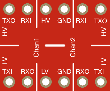
The Logic Level Converter has 8 pins, divided into two groups for the high-voltage (HV) and low-voltage (LV) sides. Below is the pinout:
| Pin Name | Description |
|---|---|
| HV | High-voltage power input (3.3V to 5V). Connect to the higher voltage source. |
| LV | Low-voltage power input (1.8V to 3.3V). Connect to the lower voltage source. |
| GND | Ground connection. Common ground for both HV and LV sides. |
| TXI1, TXI2, TXI3, TXI4 | Input pins for the low-voltage side. Signals to be shifted to the high-voltage side. |
| TXO1, TXO2, TXO3, TXO4 | Output pins for the high-voltage side. Signals shifted from the low-voltage side. |
Usage Instructions
How to Use the Logic Level Converter in a Circuit
Power Connections:
- Connect the HV pin to the high-voltage source (e.g., 5V).
- Connect the LV pin to the low-voltage source (e.g., 3.3V).
- Connect the GND pin to the common ground of both voltage sources.
Signal Connections:
- For each channel, connect the low-voltage signal to the corresponding TXI pin.
- The shifted high-voltage signal will be available at the corresponding TXO pin.
- Similarly, signals from the high-voltage side can be connected to TXO pins, and the shifted low-voltage signals will appear at the corresponding TXI pins.
Protocol-Specific Notes:
- For I2C communication, connect the SDA and SCL lines to two of the available channels (e.g., TXI1/TXO1 and TXI2/TXO2).
- Ensure pull-up resistors are present on both the high-voltage and low-voltage sides of the I2C bus.
Important Considerations and Best Practices
- Always ensure the HV and LV power inputs are connected to the correct voltage levels. Reversing these connections may damage the Logic Level Converter.
- Use appropriate pull-up resistors for I2C communication to ensure proper signal integrity.
- Avoid exceeding the maximum voltage ratings for both the high and low sides.
- Keep the ground connection common between all devices in the circuit to prevent communication issues.
Example: Connecting to an Arduino UNO
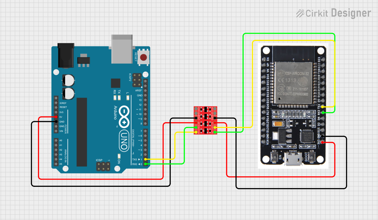
Below is an example of using the Logic Level Converter to interface a 3.3V sensor with a 5V Arduino UNO:
Circuit Connections
- Connect the Arduino's 5V pin to the HV pin of the Logic Level Converter.
- Connect the sensor's 3.3V power pin to the LV pin of the Logic Level Converter.
- Connect the Arduino's GND pin and the sensor's GND pin to the GND pin of the Logic Level Converter.
- Connect the sensor's data pin to TXI1, and connect TXO1 to the corresponding Arduino input pin.
Arduino Code Example
// Example code for reading data from a 3.3V sensor using a Logic Level Converter
// connected to an Arduino UNO (5V logic).

const int sensorPin = 2; // Arduino pin connected to TXO1 of the Logic Level Converter

void setup() {
  Serial.begin(9600); // Initialize serial communication
  pinMode(sensorPin, INPUT); // Set the sensor pin as input
}

void loop() {
  int sensorValue = digitalRead(sensorPin); // Read the sensor value
  Serial.println(sensorValue); // Print the sensor value to the Serial Monitor
  delay(500); // Wait for 500ms before reading again
}
Troubleshooting and FAQs
Common Issues and Solutions
No Signal on the Output Pins:
- Verify that the HV and LV pins are connected to the correct voltage sources.
- Ensure the ground connection is common between all devices in the circuit.
Data Corruption in I2C Communication:
- Check that pull-up resistors are present on both the high-voltage and low-voltage sides of the I2C bus.
- Ensure the data rate does not exceed the maximum supported frequency (100 kHz for I2C).
Device Overheating:
- Confirm that the voltage levels on the HV and LV pins do not exceed the specified ranges.
- Check for short circuits in the wiring.
FAQs
Q: Can the Logic Level Converter handle analog signals?
A: No, the Logic Level Converter is designed for digital signals only. For analog signals, consider using a dedicated voltage divider or level-shifting circuit.
Q: Can I use the Logic Level Converter for SPI communication?
A: Yes, the Logic Level Converter can be used for SPI communication. However, ensure that the SPI clock frequency is within the supported range for reliable operation.
Q: Do I need external pull-up resistors for GPIO signals?
A: Pull-up resistors are not required for general GPIO signals but are necessary for open-drain communication protocols like I2C.
By following this documentation, you can safely and effectively use the SparkFun Logic Level Converter in your projects.