Cirkit Designer
Your all-in-one circuit design IDE
Home /
Component Documentation
How to Use 7 inch DSI Display: Examples, Pinouts, and Specs
Introduction
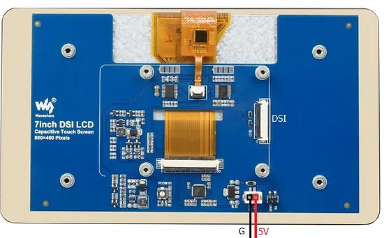
The 7 inch DSI Display is a peripheral display device designed to work with the Raspberry Pi series of single-board computers. Utilizing the Display Serial Interface (DSI), this display provides a high-quality visual output through a dedicated interface, which allows for efficient communication between the Raspberry Pi and the display. Common applications include portable computing projects, embedded systems, digital signage, and interactive kiosks.
Explore Projects Built with 7 inch DSI Display
74HC21-Based LED Display with 7-Segment Indicator
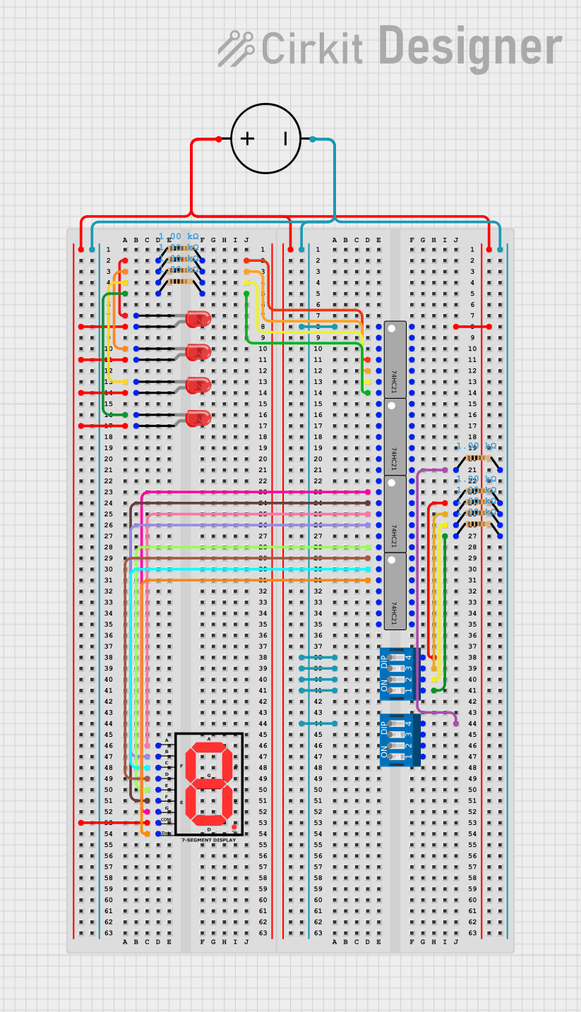
This circuit is a digital display system that uses a 7-segment display and multiple red LEDs controlled by 74HC21 logic gates and DIP switches. The LEDs are connected through resistors to the logic gates, which are powered by a DC power source, allowing for the display of various states or numbers based on the DIP switch settings.
I2C-Controlled OLED Display with External EEPROM and Interactive Pushbuttons

This is a microcontroller-based interactive device featuring a Wemos D1 Mini, an OLED display, external EEPROM, and an I/O expander. It includes user input buttons and status LEDs, with potential MIDI interface capabilities.
Arduino UNO Controlled TCS3200 Color Sensor with I2C LCD Display

This circuit features an Arduino UNO microcontroller interfaced with a TCS3200 color sensor and an I2C LCD 16x2 display. The TCS3200 color sensor's output is connected to the Arduino's digital pin D12, and its frequency scaling pins (S0-S3) are connected to digital pins D8-D11 for configuration. The LCD display communicates with the Arduino via the I2C protocol, using A4 (SDA) and A5 (SCL) for data transfer, allowing the system to display color readings or other information from the sensor.
Arduino Nano-Based GPS and Barometric Sensor with Seven Segment Display and Battery Power
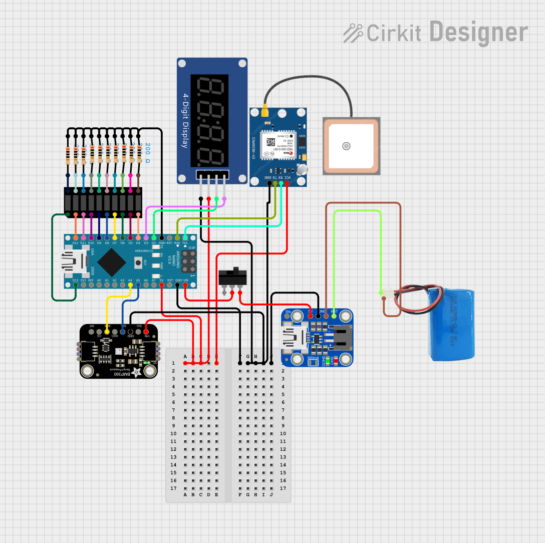
This circuit is a sensor and display system powered by an Arduino Nano, which reads data from a GPS module and a BMP390 sensor, and displays information on a seven-segment display and a bar graph. The system is powered by a 5V battery through a Mini Lipo charger, and includes a toggle switch for power control.
Explore Projects Built with 7 inch DSI Display
74HC21-Based LED Display with 7-Segment Indicator
This circuit is a digital display system that uses a 7-segment display and multiple red LEDs controlled by 74HC21 logic gates and DIP switches. The LEDs are connected through resistors to the logic gates, which are powered by a DC power source, allowing for the display of various states or numbers based on the DIP switch settings.
I2C-Controlled OLED Display with External EEPROM and Interactive Pushbuttons
This is a microcontroller-based interactive device featuring a Wemos D1 Mini, an OLED display, external EEPROM, and an I/O expander. It includes user input buttons and status LEDs, with potential MIDI interface capabilities.
Arduino UNO Controlled TCS3200 Color Sensor with I2C LCD Display
This circuit features an Arduino UNO microcontroller interfaced with a TCS3200 color sensor and an I2C LCD 16x2 display. The TCS3200 color sensor's output is connected to the Arduino's digital pin D12, and its frequency scaling pins (S0-S3) are connected to digital pins D8-D11 for configuration. The LCD display communicates with the Arduino via the I2C protocol, using A4 (SDA) and A5 (SCL) for data transfer, allowing the system to display color readings or other information from the sensor.
Arduino Nano-Based GPS and Barometric Sensor with Seven Segment Display and Battery Power
This circuit is a sensor and display system powered by an Arduino Nano, which reads data from a GPS module and a BMP390 sensor, and displays information on a seven-segment display and a bar graph. The system is powered by a 5V battery through a Mini Lipo charger, and includes a toggle switch for power control.
Technical Specifications
General Features
- Screen Size: 7 inches (diagonal)
- Resolution: 800x480 pixels
- Touchscreen: Capacitive touch (10-point multi-touch)
- Interface: MIPI DSI (Display Serial Interface)
- Backlight: LED
- Power Consumption: 500mA (maximum under normal operating conditions)
Pin Configuration and Descriptions
| Pin Number | Description | Notes |
|---|---|---|
| 1 | 5V Power | Supply power to the display |
| 2 | Ground | Ground connection |
| 3-4 | NC (No Connection) | Not used for this display |
| 5-12 | DSI Data and Control | Data lanes and control signals |
| 13-15 | Touch Interface | I2C/SPI for touch functionality |
Usage Instructions
Connecting the Display
- Power Off the Raspberry Pi: Ensure the Raspberry Pi is turned off before connecting the display to prevent any electrical damage.
- Connect the DSI Cable: Attach the DSI ribbon cable from the display to the DSI port on the Raspberry Pi. Make sure the connectors are properly aligned and the cable is securely fastened.
- Connect the Power Leads: Attach the power leads from the display to the GPIO pins on the Raspberry Pi for 5V and GND.
- Turn On the Raspberry Pi: Once the display is connected, power on the Raspberry Pi.
Configuration
- Enable DSI Display: Use the
raspi-configtool to enable the DSI display in the Raspberry Pi configuration settings. - Calibrate Touchscreen (if necessary): If the touchscreen requires calibration, use the provided calibration tools or software to ensure accurate touch input.
Best Practices
- Handle with Care: The display is a delicate component. Avoid applying pressure to the screen and handle the flex cables with care to prevent damage.
- Use a Stable Power Source: Ensure that the Raspberry Pi has a stable 5V power supply, especially when using the display, to avoid any power-related issues.
- Update Raspberry Pi Software: Keep the Raspberry Pi's software up to date to ensure compatibility and the best performance with the display.
Troubleshooting and FAQs
Common Issues
- Display Not Detected: Ensure that the DSI cable is properly connected and that the display is enabled in the Raspberry Pi configuration.
- Touchscreen Not Responding: Check the touch interface connections and ensure that the correct drivers are installed and configured.
- Image Quality Issues: If the display has poor image quality, check the resolution settings and adjust them according to the display's specifications.
FAQs
- Q: Can I use the display with any Raspberry Pi model?
- A: The display is compatible with Raspberry Pi models that have a DSI port. Check your model's specifications for compatibility.
- Q: Do I need an external power supply for the display?
- A: No, the display can be powered directly from the Raspberry Pi's GPIO pins.
Example Code for Raspberry Pi
Below is an example of how to initialize the display using Python with the RPi.GPIO library. This is a simple example and assumes you have the necessary libraries installed.
import RPi.GPIO as GPIO
import time
Setup GPIO
GPIO.setmode(GPIO.BCM) GPIO.setup(18, GPIO.OUT)
Turn on the backlight
GPIO.output(18, GPIO.HIGH)
Your display initialization code here
Remember to cleanup GPIO pins after use
GPIO.cleanup()
**Note:** This code snippet is for demonstration purposes only. The actual initialization of the display will depend on the specific libraries and drivers you are using.

For further assistance, consult the Raspberry Pi community forums or the manufacturer's support resources.