
How to Use mic: Examples, Pinouts, and Specs
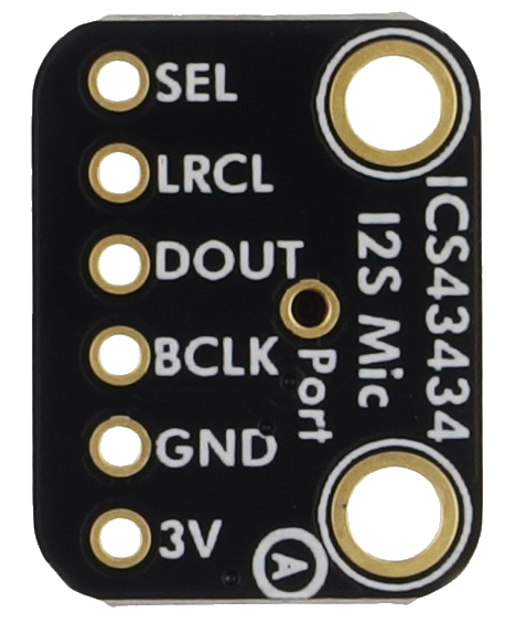
 Design with mic in Cirkit Designer
Introduction
A microphone (mic) is a device that converts sound waves into electrical signals, enabling the capture, amplification, and processing of audio. Microphones are widely used in applications such as audio recording, broadcasting, communication systems, voice recognition, and sound measurement. They are essential components in devices like smartphones, computers, audio equipment, and hearing aids.
Explore Projects Built with mic
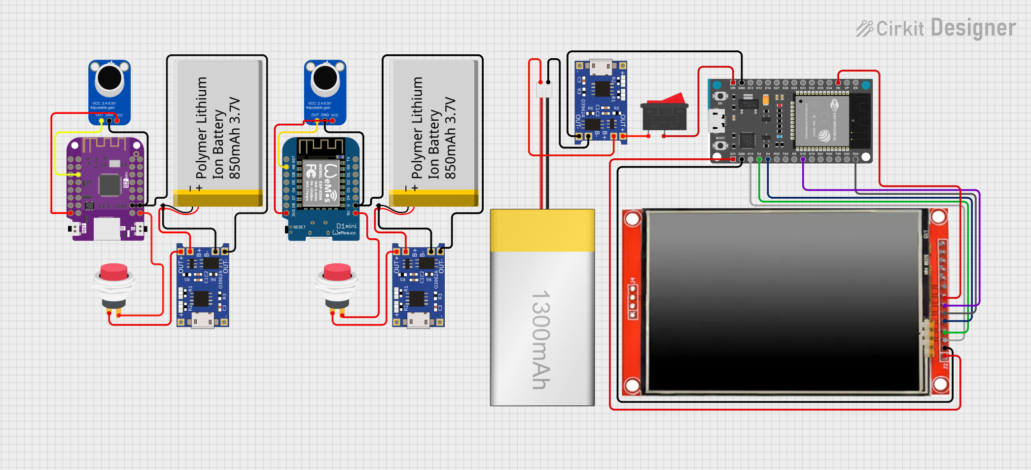 Open Project in Cirkit Designer
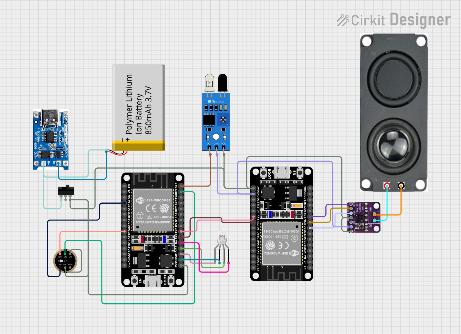 Open Project in Cirkit Designer
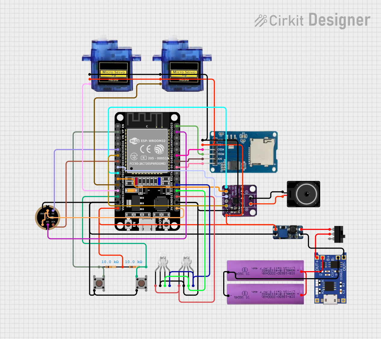 Open Project in Cirkit Designer
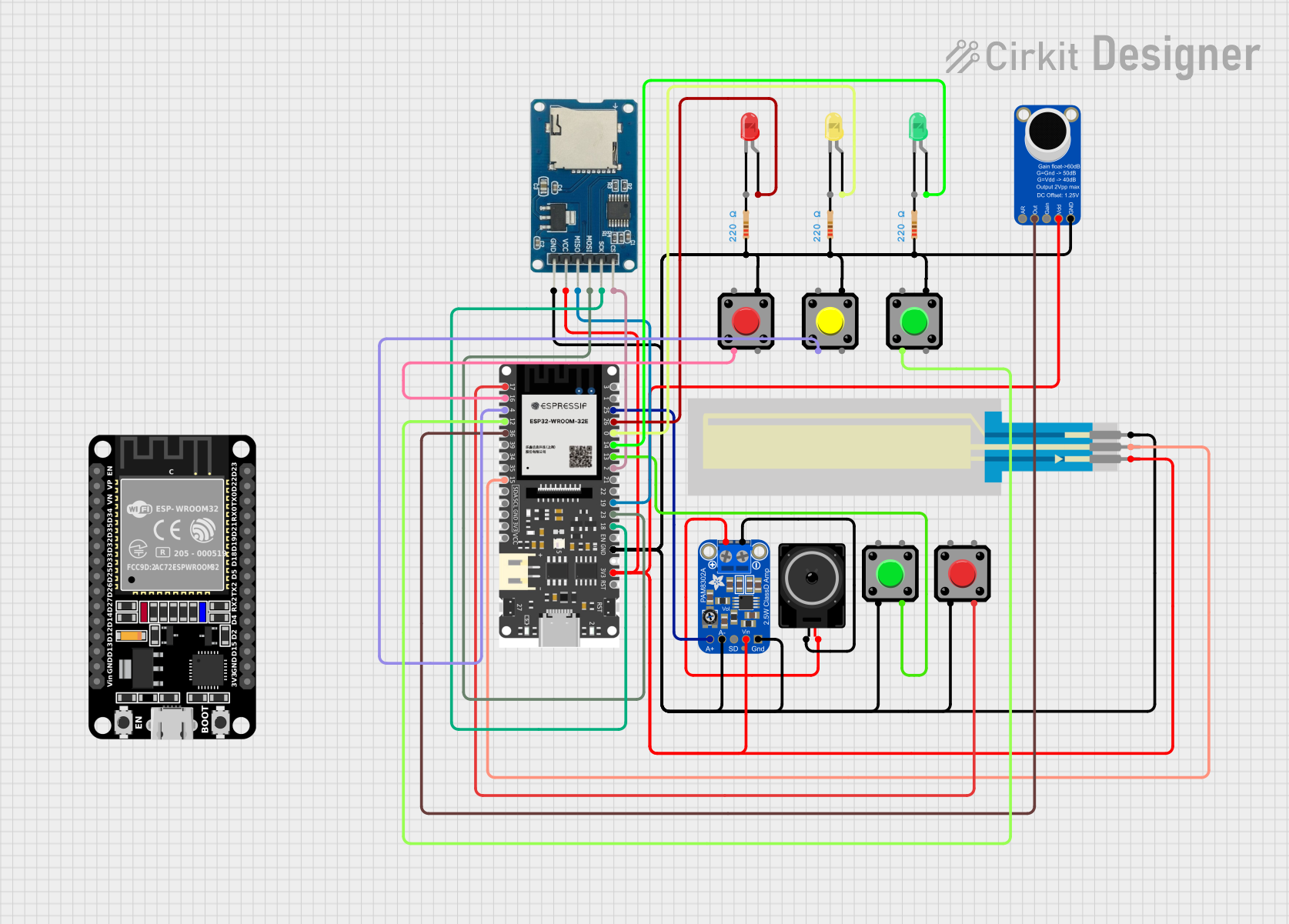 Open Project in Cirkit Designer
Explore Projects Built with mic
Open Project in Cirkit DesignerOpen Project in Cirkit DesignerOpen Project in Cirkit DesignerOpen Project in Cirkit DesignerTechnical Specifications
Below are the general technical specifications for a typical microphone. Note that specific values may vary depending on the exact model and manufacturer.
Key Specifications
- Manufacturer: MIC
- Part ID: MIC
- Type: Electret Condenser Microphone (common type)
- Operating Voltage: 1.5V to 10V DC
- Current Consumption: 0.5 mA to 1.5 mA
- Sensitivity: -44 dB ± 3 dB (at 1 kHz, 1 Pa)
- Frequency Response: 20 Hz to 20 kHz
- Impedance: 2.2 kΩ (typical)
- Signal-to-Noise Ratio (SNR): ≥ 60 dB
- Directivity: Omnidirectional (captures sound from all directions)
- Output Type: Analog
Pin Configuration and Descriptions
The microphone typically has two or three pins for connection. Below is the pin configuration:
| Pin | Name | Description |
|---|---|---|
| 1 | V+ | Positive power supply pin (connect to 1.5V–10V DC). |
| 2 | GND | Ground pin (connect to circuit ground). |
| 3 | Signal Out | Analog audio signal output (connect to amplifier or microcontroller input). |
Note: Some microphones may have only two pins (V+ and GND), with the signal output integrated into the V+ pin.
Usage Instructions
How to Use the Microphone in a Circuit
- Power Supply: Connect the V+ pin to a DC voltage source within the operating range (e.g., 5V). Ensure the power supply is stable and noise-free.
- Ground Connection: Connect the GND pin to the circuit ground.
- Signal Output: Connect the Signal Out pin to an amplifier, ADC (Analog-to-Digital Converter), or microcontroller input for further processing.
- Decoupling Capacitor: Place a decoupling capacitor (e.g., 10 µF) between the Signal Out pin and the input of the next stage to block DC offset.
- Amplification: Use an operational amplifier (op-amp) or a dedicated microphone amplifier circuit to boost the weak audio signal for further processing.
Important Considerations and Best Practices
- Avoid Noise Interference: Use shielded cables and proper grounding to minimize noise and interference.
- Placement: Position the microphone away from sources of vibration or loud noise to avoid distortion.
- Impedance Matching: Ensure the input impedance of the connected circuit matches the microphone's output impedance for optimal performance.
- Power Supply Filtering: Use a bypass capacitor (e.g., 0.1 µF) near the V+ pin to filter out power supply noise.
Example: Connecting a Microphone to an Arduino UNO
Below is an example of how to connect a microphone to an Arduino UNO for basic audio signal reading:
Circuit Connections
- Connect the microphone's V+ pin to the Arduino's 5V pin.
- Connect the GND pin to the Arduino's GND pin.
- Connect the Signal Out pin to an analog input pin on the Arduino (e.g., A0).
Arduino Code
// Microphone signal reading example with Arduino UNO
// Connect the microphone's Signal Out pin to A0 on the Arduino

const int micPin = A0;  // Microphone connected to analog pin A0
int micValue = 0;       // Variable to store microphone signal value

void setup() {
  Serial.begin(9600);  // Initialize serial communication at 9600 baud
}

void loop() {
  micValue = analogRead(micPin);  // Read the analog value from the microphone
  Serial.println(micValue);      // Print the value to the Serial Monitor

  delay(10);  // Small delay to stabilize readings
}
Note: The analog values read from the microphone will vary based on the sound intensity. For more advanced applications, you can process the signal further (e.g., using FFT for frequency analysis).
Troubleshooting and FAQs
Common Issues and Solutions
No Signal Output:
- Ensure the microphone is powered correctly (check V+ and GND connections).
- Verify that the Signal Out pin is connected to the correct input.
- Check for loose or broken wires.
Distorted Audio:
- Reduce the input sound level or move the microphone further from the sound source.
- Ensure the amplifier gain is not set too high.
Excessive Noise:
- Use shielded cables and proper grounding.
- Add a low-pass filter to remove high-frequency noise.
Low Sensitivity:
- Verify the power supply voltage is within the recommended range.
- Check for impedance mismatches between the microphone and the connected circuit.
FAQs
Q: Can I connect the microphone directly to a speaker?
A: No, the microphone's output signal is too weak to drive a speaker directly. You need an amplifier circuit.Q: What type of capacitor should I use for decoupling?
A: A 10 µF electrolytic capacitor is commonly used for decoupling the microphone's signal output.Q: Can this microphone be used for voice recognition?
A: Yes, this microphone can capture audio for voice recognition applications when paired with appropriate signal processing hardware and software.Q: How do I measure the frequency of the sound captured by the microphone?
A: Use an ADC to digitize the microphone's output and apply an FFT (Fast Fourier Transform) algorithm to analyze the frequency components.
By following this documentation, you can effectively integrate and troubleshoot the microphone in your projects.