How to Use LOOP DETECTOR: Examples, Pinouts, and Specs
Introduction
The MT470 Loop Detector is an electronic device manufactured by NORTECH, designed to detect the presence of vehicles at intersections or similar traffic scenarios. It operates by sensing changes in the inductance of a wire loop that is embedded in the pavement. When a vehicle passes over or stops on the loop, the detector triggers a response, typically to control traffic signals or activate barrier mechanisms.
Explore Projects Built with LOOP DETECTOR
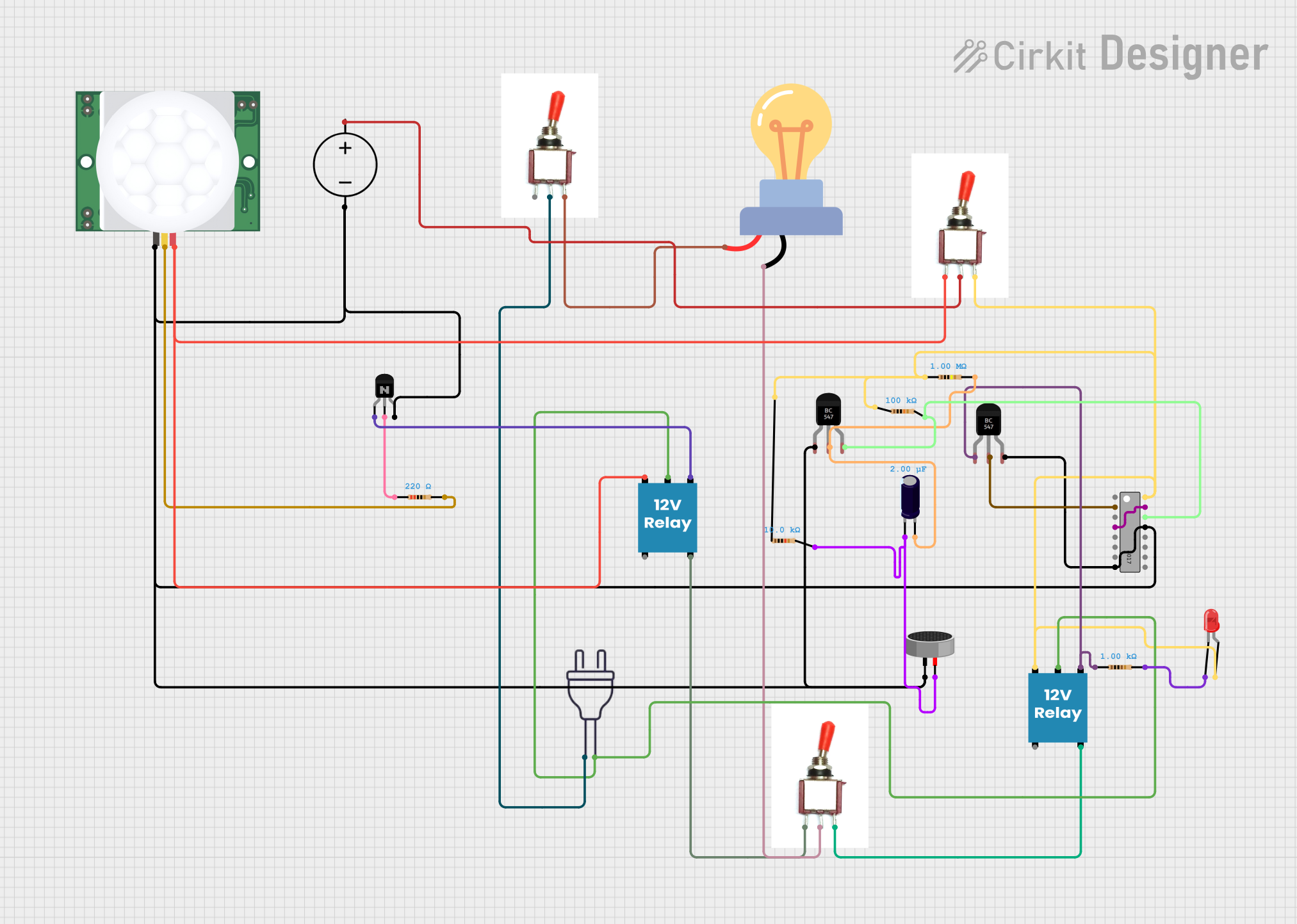
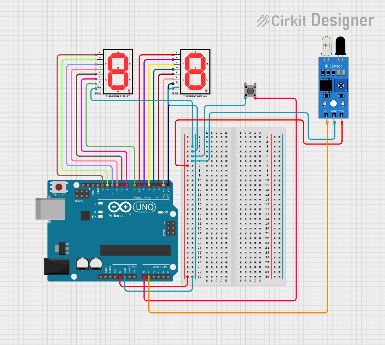
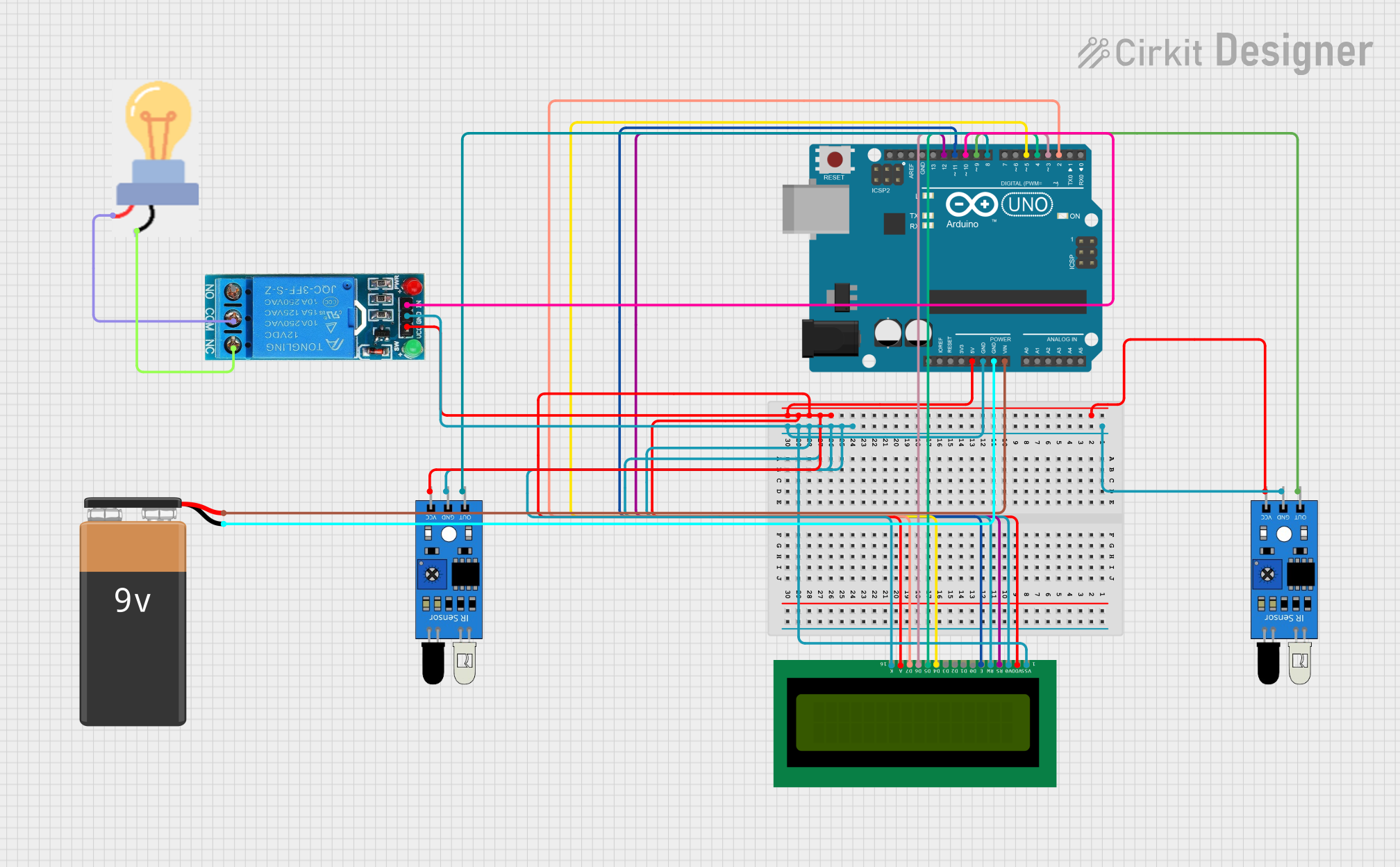
Explore Projects Built with LOOP DETECTOR
Common Applications and Use Cases
- Traffic signal control at intersections
- Counting and monitoring of vehicles
- Activation of barriers or gates in parking facilities
- Industrial automation where vehicle detection is necessary
Technical Specifications
Key Technical Details
- Supply Voltage: 10 to 30 VDC or 12 to 24 VAC
- Current Consumption: Typically 45 mA
- Frequency Range: 20 kHz to 170 kHz (adjustable)
- Sensitivity: 0.01% to 0.99% ΔL/L (adjustable)
- Operating Temperature: -40°C to +70°C
- Output: Relay output with NO, NC, and COM contacts
- Dimensions: 78 x 40 x 108 mm (H x W x D)
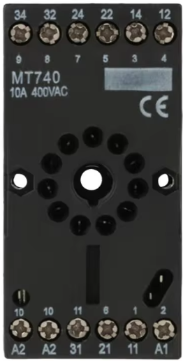
Pin Configuration and Descriptions
| Pin Number | Description | Notes |
|---|---|---|
| 1 | Power Supply + | Connect to 10-30 VDC or 12-24 VAC |
| 2 | Power Supply - | Ground connection |
| 3 | Relay Normally Open (NO) | Relay contact opens when loop is inactive |
| 4 | Relay Common (COM) | Common relay contact |
| 5 | Relay Normally Closed (NC) | Relay contact closes when loop is inactive |
| 6 | Frequency Adjust | Set loop frequency |
| 7 | Sensitivity Adjust | Set detection sensitivity |
| 8 | Loop Connection 1 | Connect to loop wire 1 |
| 9 | Loop Connection 2 | Connect to loop wire 2 |
Usage Instructions
How to Use the MT470 Loop Detector in a Circuit
- Loop Installation: Install the inductive loop in the pavement following the manufacturer's guidelines for size and depth.
- Wiring: Connect the loop wires to pins 8 and 9 on the MT470. Ensure the power supply is connected to pins 1 (+) and 2 (-).
- Adjustments: Use the frequency and sensitivity adjustment controls (pins 6 and 7) to calibrate the detector for the specific loop characteristics and environmental conditions.
- Output Connection: Connect the relay output pins (3, 4, and 5) to the control system or signaling device.
Important Considerations and Best Practices
- Ensure the loop is properly installed and sealed to prevent moisture ingress which can affect performance.
- Avoid running the loop wires parallel to high voltage cables to prevent interference.
- Regularly check the loop integrity and connections to prevent false detections or failures.
- Use shielded cables for loop connections to minimize electromagnetic interference.
Troubleshooting and FAQs
Common Issues
- False Detections: Adjust the sensitivity and check for interference from nearby electrical sources.
- No Detections: Verify the integrity of the loop and connections. Check the power supply and ensure the detector is properly calibrated.
- Intermittent Operation: Inspect the loop for damage and ensure the detector settings are appropriate for the environment.
Solutions and Tips for Troubleshooting
- Loop Failure: Use an inductance meter to check the loop. Replace if necessary.
- Power Issues: Confirm the supply voltage is within the specified range and the connections are secure.
- Calibration: Follow the manufacturer's instructions to recalibrate the detector if the environment or loop characteristics change.
FAQs
Q: Can the MT470 be used with any size loop? A: The MT470 is designed to work with a range of loop sizes, but the loop dimensions should be within the manufacturer's recommended guidelines for optimal performance.
Q: How do I know if the loop detector is functioning correctly? A: The MT470 typically has LED indicators that show the status of the loop and detection. Refer to the manufacturer's manual for specific indicator meanings.
Q: What is the maximum length of cable that can be used between the loop and the detector? A: The maximum cable length depends on the wire gauge and the total loop resistance. Consult the manufacturer's specifications for detailed information.
Q: Can the MT470 operate in extreme weather conditions? A: The MT470 is rated for operation in temperatures ranging from -40°C to +70°C. However, ensure that the loop installation is suitable for the local environmental conditions.
Example Code for Arduino UNO Connection
// Example code to demonstrate how to interface the MT470 Loop Detector with an Arduino UNO
// The relay output from the MT470 is connected to digital pin 2 on the Arduino

const int loopDetectorPin = 2; // MT470 relay output connected to digital pin 2
const int ledPin = 13;         // Onboard LED connected to digital pin 13

void setup() {
  pinMode(loopDetectorPin, INPUT_PULLUP); // Set the loop detector pin as input with pull-up
  pinMode(ledPin, OUTPUT);               // Set the LED pin as output
}

void loop() {
  // Check if the loop detector's relay is closed (vehicle detected)
  if (digitalRead(loopDetectorPin) == LOW) {
    digitalWrite(ledPin, HIGH); // Turn on the LED
  } else {
    digitalWrite(ledPin, LOW);  // Turn off the LED
  }
}
This example assumes that the relay output from the MT470 is connected to the Arduino's digital pin 2. When the loop detector detects a vehicle, the relay closes, pulling the input to LOW and turning on the onboard LED. When no vehicle is detected, the relay is open, and the LED is off.