How to Use Adafruit Stereo 3W Speaker Bonnet: Examples, Pinouts, and Specs
Introduction
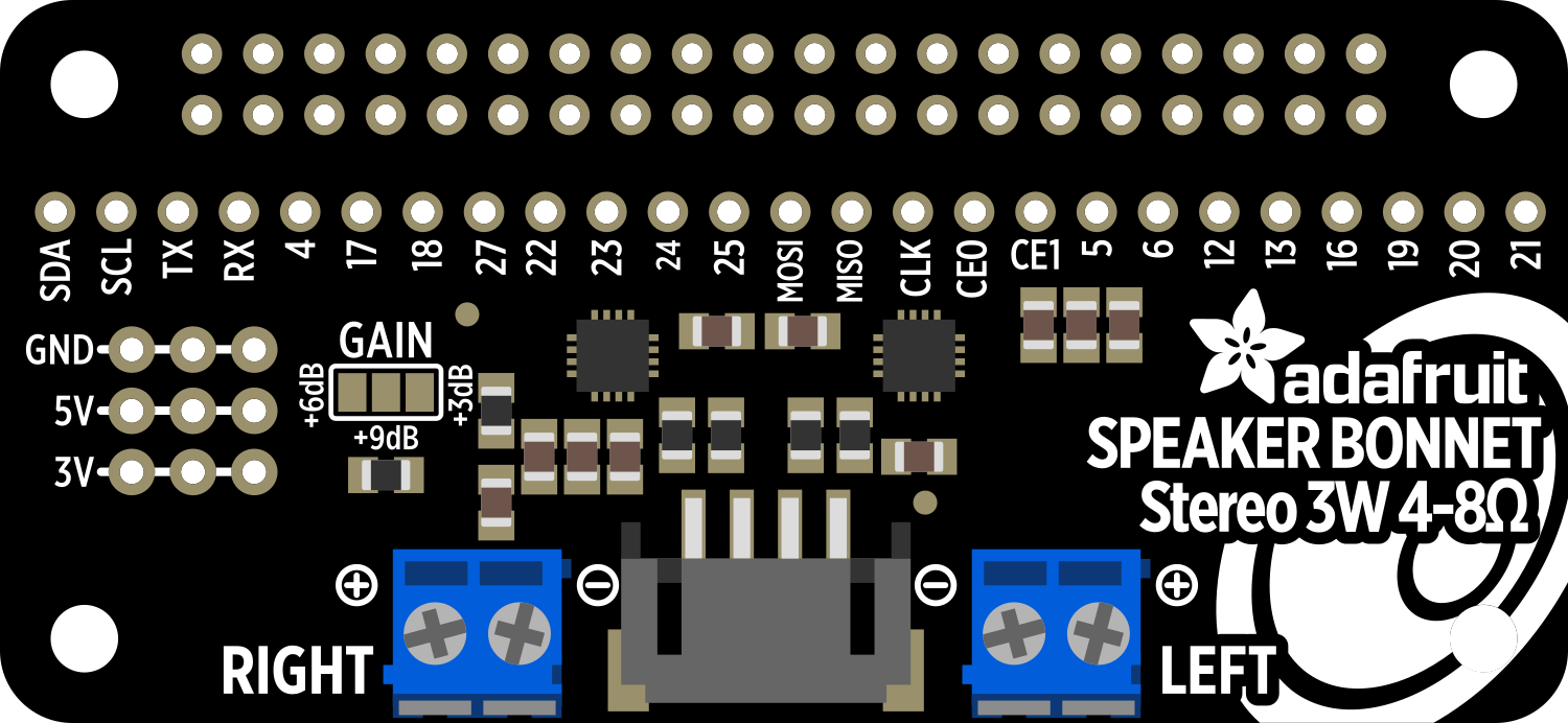
The Adafruit Stereo 3W Speaker Bonnet is an audio accessory designed for the Raspberry Pi, which provides high-quality stereo sound. This HAT (Hardware Attached on Top) features a PCM5102A stereo DAC (Digital-to-Analog Converter) for excellent audio reproduction and includes a built-in 3W per channel amplifier, capable of driving speakers directly. It is ideal for projects that require audio output, such as home media centers, digital jukeboxes, or interactive art installations.
Explore Projects Built with Adafruit Stereo 3W Speaker Bonnet
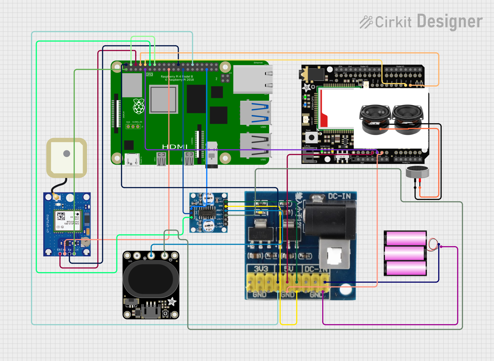
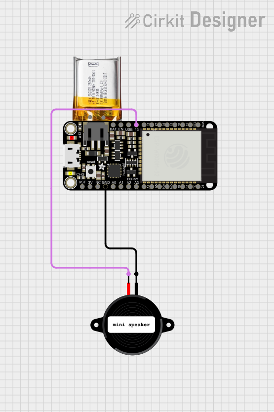
Explore Projects Built with Adafruit Stereo 3W Speaker Bonnet
Technical Specifications
Key Features
- DAC Chip: PCM5102A
- Output Power: 3W per channel into 4Ω speakers
- Audio Output: Stereo
- Interface: I2S digital audio interface
- Compatibility: Raspberry Pi Zero, A+, B+, 2, 3, 4 models
- Dimensions: 65mm x 30mm x 18mm
Pin Configuration and Descriptions
| Pin Number | Function | Description |
|---|---|---|
| 1 | 5V | Power supply for the amplifier |
| 2 | 3.3V | Power supply for the DAC |
| 3 | GND | Ground |
| 4 | LRCLK | Left/Right Clock (Audio data word clock) |
| 5 | BCLK | Bit Clock (Audio sample clock) |
| 6 | DIN | Data Input (Audio data input) |
| 7 | GPIO | General Purpose Input/Output for control |
| 8 | Speaker Output | Positive terminal for the left speaker |
| 9 | Speaker Output | Negative terminal for the left speaker |
| 10 | Speaker Output | Positive terminal for the right speaker |
| 11 | Speaker Output | Negative terminal for the right speaker |
Usage Instructions
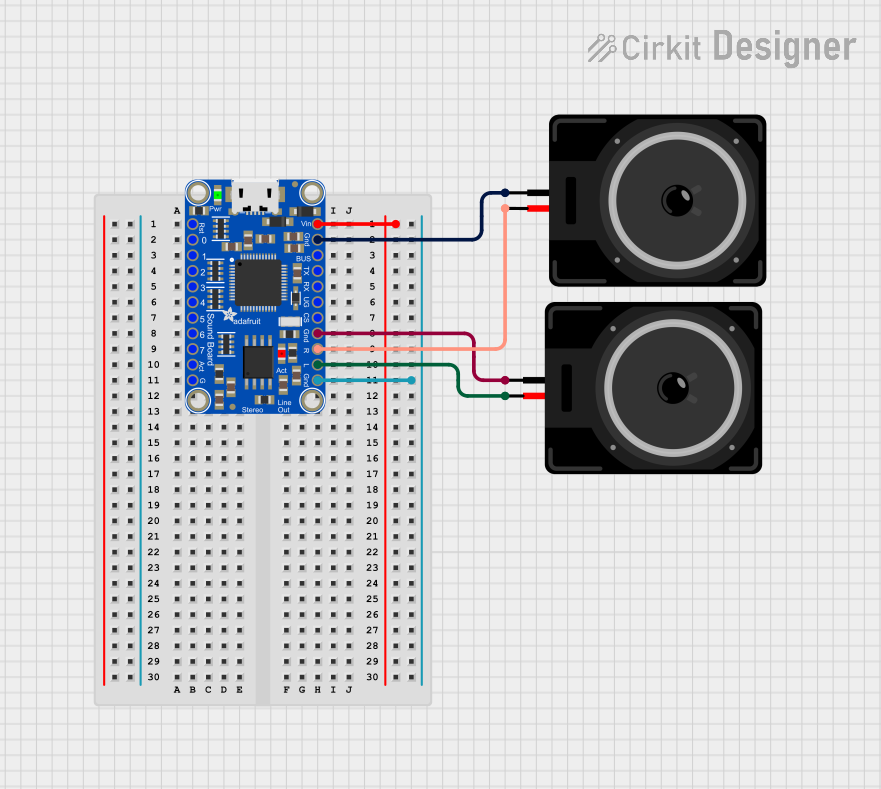
Connecting the Bonnet to a Raspberry Pi
- Power Off the Pi: Ensure that your Raspberry Pi is turned off before connecting the bonnet.
- Attach the Bonnet: Align the GPIO header of the bonnet with the pins on the Raspberry Pi and gently press down to connect.
- Connect Speakers: Attach speakers to the speaker terminals on the bonnet, ensuring correct polarity.
Software Configuration
To use the Adafruit Stereo 3W Speaker Bonnet, you'll need to configure the audio settings on your Raspberry Pi:
Update the Pi: Ensure your Raspberry Pi is up to date with the latest version of the operating system and firmware.
sudo apt-get update
sudo apt-get upgrade
Install Dependencies: Install the necessary software packages.
sudo apt-get install -y python-smbus i2c-toolsConfigure the Audio Output: Edit the
/boot/config.txtfile to set up the I2S audio.sudo nano /boot/config.txtAdd the following lines to the file:
dtoverlay=hifiberry-dac
dtoverlay=i2s-mmap
Reboot the Pi: After saving the changes, reboot your Raspberry Pi.
sudo rebootTest the Audio Output: Once the Pi has rebooted, you can test the audio output.
speaker-test -c2 -t wav
Best Practices
- Use speakers with an impedance of 4Ω for optimal performance.
- Avoid disconnecting or connecting speakers while the Pi is powered to prevent damage.
- Ensure proper ventilation around the bonnet to avoid overheating.
Troubleshooting and FAQs
Common Issues
- No Sound: Check the speaker connections and ensure the Raspberry Pi audio output is configured correctly.
- Distorted Sound: This may be due to incorrect speaker impedance or volume set too high. Adjust the volume and verify speaker specifications.
- Overheating: Ensure adequate airflow around the bonnet and avoid enclosing it in a tight space without ventilation.
FAQs
Q: Can I use 8Ω speakers with this bonnet? A: Yes, but the output power will be lower than with 4Ω speakers.
Q: Does this bonnet support audio input? A: No, the Adafruit Stereo 3W Speaker Bonnet is designed for audio output only.
Q: Can I control the volume through software?
A: Yes, you can control the volume using the alsamixer or any other audio control software compatible with the Raspberry Pi.
For further assistance, refer to the Adafruit support forums or the Raspberry Pi community forums.