Cirkit Designer Logo
Cirkit Designer
Your all-in-one circuit design IDE
Home / 
Component Documentation

How to Use Waveshare ESP32-S3 Mini Development Board, Based on ESP32-S3FH4R2 Dual-Core Processor, 240MHz Running Frequency, 2.4GHz Wi-Fi & Bluetooth 5: Examples, Pinouts, and Specs

Image of Waveshare ESP32-S3 Mini Development Board, Based on ESP32-S3FH4R2 Dual-Core Processor, 240MHz Running Frequency, 2.4GHz Wi-Fi & Bluetooth 5
Cirkit Designer LogoDesign with Waveshare ESP32-S3 Mini Development Board, Based on ESP32-S3FH4R2 Dual-Core Processor, 240MHz Running Frequency, 2.4GHz Wi-Fi & Bluetooth 5 in Cirkit Designer

Introduction

The Waveshare ESP32-S3 Mini Development Board is a compact and versatile development platform based on the ESP32-S3FH4R2 dual-core processor. With a maximum clock speed of 240MHz, this board is designed for high-performance IoT applications. It supports 2.4GHz Wi-Fi and Bluetooth 5, enabling seamless wireless communication. Its small form factor and robust features make it ideal for smart home devices, wearable electronics, industrial automation, and other IoT projects.

Explore Projects Built with Waveshare ESP32-S3 Mini Development Board, Based on ESP32-S3FH4R2 Dual-Core Processor, 240MHz Running Frequency, 2.4GHz Wi-Fi & Bluetooth 5

Use Cirkit Designer to design, explore, and prototype these projects online. Some projects support real-time simulation. Click "Open Project" to start designing instantly!
ESP32-Based Data Display and RF Communication System
Image of Esp_Disp2: A project utilizing Waveshare ESP32-S3 Mini Development Board, Based on ESP32-S3FH4R2 Dual-Core Processor, 240MHz Running Frequency, 2.4GHz Wi-Fi & Bluetooth 5 in a practical application
This circuit features an ESP32 microcontroller connected to an ili9341 TFT display, an SD card module, and an E07-M1101D RF transceiver module. The ESP32 controls the display via GPIO pins and communicates with both the SD card and the RF module using SPI communication. The circuit is likely designed for applications requiring a user interface, data storage, and wireless communication capabilities.
Cirkit Designer LogoOpen Project in Cirkit Designer
ESP32-Based RF Communication System with 433 MHz Modules
Image of 433 mhz: A project utilizing Waveshare ESP32-S3 Mini Development Board, Based on ESP32-S3FH4R2 Dual-Core Processor, 240MHz Running Frequency, 2.4GHz Wi-Fi & Bluetooth 5 in a practical application
This circuit comprises an ESP32 microcontroller connected to a 433 MHz RF transmitter and receiver pair. The ESP32 is programmed to receive and decode RF signals through the receiver module, as well as send RF signals via the transmitter module. Additionally, the ESP32 can communicate with a Bluetooth device to exchange commands and data, and it uses an LED for status indication.
Cirkit Designer LogoOpen Project in Cirkit Designer
ESP32C3 and LoRa-Enabled Environmental Sensing Node
Image of temperature_KA: A project utilizing Waveshare ESP32-S3 Mini Development Board, Based on ESP32-S3FH4R2 Dual-Core Processor, 240MHz Running Frequency, 2.4GHz Wi-Fi & Bluetooth 5 in a practical application
This circuit features an ESP32C3 Supermini microcontroller connected to a LORA_RA02 module and a DHT11 temperature and humidity sensor. The ESP32C3 handles communication with the LORA module via SPI (using GPIO05, GPIO06, GPIO10, and GPIO04 for MISO, MOSI, NSS, and SCK respectively) and GPIO01 and GPIO02 for additional control signals. The DHT11 sensor is interfaced through GPIO03 for data reading, and all components share a common power supply through the 3.3V and GND pins.
Cirkit Designer LogoOpen Project in Cirkit Designer
ESP32-S3 Based Vibration Detection System with TFT Display and Power Backup
Image of IOT Thesis: A project utilizing Waveshare ESP32-S3 Mini Development Board, Based on ESP32-S3FH4R2 Dual-Core Processor, 240MHz Running Frequency, 2.4GHz Wi-Fi & Bluetooth 5 in a practical application
This circuit features an ESP32-S3 microcontroller connected to various peripherals including an ADXL355 accelerometer, an SW-420 vibration sensor, a buzzer module, and an ILI9341 TFT display. The ESP32-S3 manages sensor inputs and provides output to the display and buzzer. Power management is handled by a 12V to 5V step-down converter, and a UPS ensures uninterrupted power supply, with a rocker switch to control the power flow.
Cirkit Designer LogoOpen Project in Cirkit Designer

Explore Projects Built with Waveshare ESP32-S3 Mini Development Board, Based on ESP32-S3FH4R2 Dual-Core Processor, 240MHz Running Frequency, 2.4GHz Wi-Fi & Bluetooth 5

Use Cirkit Designer to design, explore, and prototype these projects online. Some projects support real-time simulation. Click "Open Project" to start designing instantly!
Image of Esp_Disp2: A project utilizing Waveshare ESP32-S3 Mini Development Board, Based on ESP32-S3FH4R2 Dual-Core Processor, 240MHz Running Frequency, 2.4GHz Wi-Fi & Bluetooth 5 in a practical application
ESP32-Based Data Display and RF Communication System
This circuit features an ESP32 microcontroller connected to an ili9341 TFT display, an SD card module, and an E07-M1101D RF transceiver module. The ESP32 controls the display via GPIO pins and communicates with both the SD card and the RF module using SPI communication. The circuit is likely designed for applications requiring a user interface, data storage, and wireless communication capabilities.
Cirkit Designer LogoOpen Project in Cirkit Designer
Image of 433 mhz: A project utilizing Waveshare ESP32-S3 Mini Development Board, Based on ESP32-S3FH4R2 Dual-Core Processor, 240MHz Running Frequency, 2.4GHz Wi-Fi & Bluetooth 5 in a practical application
ESP32-Based RF Communication System with 433 MHz Modules
This circuit comprises an ESP32 microcontroller connected to a 433 MHz RF transmitter and receiver pair. The ESP32 is programmed to receive and decode RF signals through the receiver module, as well as send RF signals via the transmitter module. Additionally, the ESP32 can communicate with a Bluetooth device to exchange commands and data, and it uses an LED for status indication.
Cirkit Designer LogoOpen Project in Cirkit Designer
Image of temperature_KA: A project utilizing Waveshare ESP32-S3 Mini Development Board, Based on ESP32-S3FH4R2 Dual-Core Processor, 240MHz Running Frequency, 2.4GHz Wi-Fi & Bluetooth 5 in a practical application
ESP32C3 and LoRa-Enabled Environmental Sensing Node
This circuit features an ESP32C3 Supermini microcontroller connected to a LORA_RA02 module and a DHT11 temperature and humidity sensor. The ESP32C3 handles communication with the LORA module via SPI (using GPIO05, GPIO06, GPIO10, and GPIO04 for MISO, MOSI, NSS, and SCK respectively) and GPIO01 and GPIO02 for additional control signals. The DHT11 sensor is interfaced through GPIO03 for data reading, and all components share a common power supply through the 3.3V and GND pins.
Cirkit Designer LogoOpen Project in Cirkit Designer
Image of IOT Thesis: A project utilizing Waveshare ESP32-S3 Mini Development Board, Based on ESP32-S3FH4R2 Dual-Core Processor, 240MHz Running Frequency, 2.4GHz Wi-Fi & Bluetooth 5 in a practical application
ESP32-S3 Based Vibration Detection System with TFT Display and Power Backup
This circuit features an ESP32-S3 microcontroller connected to various peripherals including an ADXL355 accelerometer, an SW-420 vibration sensor, a buzzer module, and an ILI9341 TFT display. The ESP32-S3 manages sensor inputs and provides output to the display and buzzer. Power management is handled by a 12V to 5V step-down converter, and a UPS ensures uninterrupted power supply, with a rocker switch to control the power flow.
Cirkit Designer LogoOpen Project in Cirkit Designer

Common Applications and Use Cases

  • Smart home automation systems
  • Wearable devices
  • Industrial IoT (IIoT) applications
  • Wireless sensor networks
  • Prototyping for AI and machine learning at the edge
  • Bluetooth-enabled devices

Technical Specifications

Key Technical Details

  • Processor: ESP32-S3FH4R2 dual-core processor
  • Clock Speed: Up to 240MHz
  • Wireless Connectivity: 2.4GHz Wi-Fi and Bluetooth 5
  • Flash Memory: 4MB
  • SRAM: 512KB
  • GPIO Pins: 27 (multipurpose)
  • Operating Voltage: 3.3V
  • Power Supply: USB Type-C (5V input)
  • Dimensions: 51mm x 25.4mm
  • Operating Temperature: -40°C to 85°C

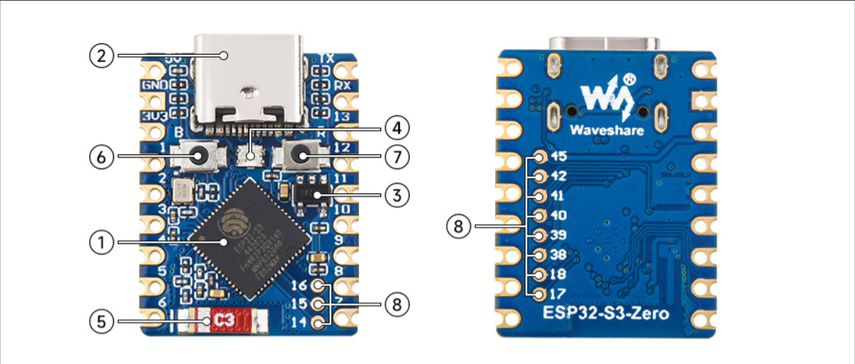
Pin Configuration and Descriptions

The Waveshare ESP32-S3 Mini Development Board features a 2x15 pin header layout. Below is the pin configuration:

Pin Name Description
1 3V3 3.3V power output
2 GND Ground
3 IO0 GPIO0, can be used for input/output or boot mode selection
4 IO1 GPIO1, general-purpose input/output
5 IO2 GPIO2, general-purpose input/output
6 IO3 GPIO3, general-purpose input/output
7 IO4 GPIO4, general-purpose input/output
8 IO5 GPIO5, general-purpose input/output
9 IO12 GPIO12, general-purpose input/output
10 IO13 GPIO13, general-purpose input/output
11 IO14 GPIO14, general-purpose input/output
12 IO15 GPIO15, general-purpose input/output
13 IO16 GPIO16, general-purpose input/output
14 IO17 GPIO17, general-purpose input/output
15 EN Enable pin, used to reset the board
16 USB_DM USB D- signal
17 USB_DP USB D+ signal
18 IO18 GPIO18, general-purpose input/output
19 IO19 GPIO19, general-purpose input/output
20 IO20 GPIO20, general-purpose input/output
21 IO21 GPIO21, general-purpose input/output
22 IO22 GPIO22, general-purpose input/output
23 IO23 GPIO23, general-purpose input/output
24 IO24 GPIO24, general-purpose input/output
25 IO25 GPIO25, general-purpose input/output
26 IO26 GPIO26, general-purpose input/output
27 IO27 GPIO27, general-purpose input/output
28 GND Ground
29 5V 5V power input
30 VIN Voltage input (external power supply)

Usage Instructions

How to Use the Component in a Circuit

  1. Powering the Board: Connect the board to a USB Type-C cable for power and programming. Ensure the power source provides 5V.
  2. Programming: Use the Arduino IDE, ESP-IDF, or other compatible development environments to program the board. Install the necessary ESP32-S3 board support package.
  3. Connecting Peripherals: Use the GPIO pins to connect sensors, actuators, or other peripherals. Ensure the voltage levels are compatible (3.3V logic).
  4. Wireless Communication: Configure the Wi-Fi and Bluetooth settings in your code to enable wireless communication.

Important Considerations and Best Practices

  • Voltage Levels: The GPIO pins operate at 3.3V. Avoid connecting 5V signals directly to the pins to prevent damage.
  • Boot Mode: To enter boot mode, hold the IO0 pin low while resetting the board.
  • Power Supply: If using an external power supply, ensure it provides a stable 5V input to the VIN pin.
  • Heat Management: While the board is designed to operate in a wide temperature range, ensure proper ventilation for high-performance applications.

Example Code for Arduino UNO Integration

Below is an example of how to use the Waveshare ESP32-S3 Mini Development Board to connect to a Wi-Fi network and blink an LED:

#include <WiFi.h> // Include the Wi-Fi library

// Replace with your network credentials
const char* ssid = "Your_SSID";
const char* password = "Your_PASSWORD";

const int ledPin = 2; // GPIO2 is connected to the onboard LED

void setup() {
  pinMode(ledPin, OUTPUT); // Set the LED pin as an output
  Serial.begin(115200);    // Start the serial communication

  // Connect to Wi-Fi
  Serial.print("Connecting to Wi-Fi");
  WiFi.begin(ssid, password);
  while (WiFi.status() != WL_CONNECTED) {
    delay(500);
    Serial.print(".");
  }
  Serial.println("\nWi-Fi connected!");
}

void loop() {
  digitalWrite(ledPin, HIGH); // Turn the LED on
  delay(1000);                // Wait for 1 second
  digitalWrite(ledPin, LOW);  // Turn the LED off
  delay(1000);                // Wait for 1 second
}

Troubleshooting and FAQs

Common Issues Users Might Face

  1. Board Not Detected by Computer:

    • Ensure the USB cable is functional and supports data transfer.
    • Verify that the correct drivers for the ESP32-S3 are installed on your computer.
  2. Wi-Fi Connection Fails:

    • Double-check the SSID and password in your code.
    • Ensure the Wi-Fi network is within range and operational.
  3. GPIO Pin Not Responding:

    • Confirm that the pin is not being used for another function (e.g., boot mode).
    • Check for loose or incorrect connections in your circuit.
  4. Board Not Entering Boot Mode:

    • Ensure the IO0 pin is held low while resetting the board.

Solutions and Tips for Troubleshooting

  • Use a multimeter to verify power supply voltages.
  • Check the serial monitor for error messages during programming.
  • Update the ESP32-S3 board support package in your development environment to the latest version.
  • Refer to the Waveshare documentation for additional technical details and support.