Cirkit Designer Logo
Cirkit Designer
Your all-in-one circuit design IDE
Home / 
Component Documentation

How to Use LYPR540AH: Examples, Pinouts, and Specs

Image of LYPR540AH
Cirkit Designer LogoDesign with LYPR540AH in Cirkit Designer

Introduction

The LYPR540AH is a high-performance linear position sensor designed to deliver accurate position feedback in a wide range of applications. Its robust design and high resolution make it ideal for use in robotics, automation, and industrial machinery, where precise motion control is critical. This sensor is engineered to withstand demanding environments, ensuring reliable operation in both commercial and industrial settings.

Explore Projects Built with LYPR540AH

Use Cirkit Designer to design, explore, and prototype these projects online. Some projects support real-time simulation. Click "Open Project" to start designing instantly!
Arduino Mega 2560 Based Security System with Fingerprint Authentication and SMS Alerts
Image of Door security system: A project utilizing LYPR540AH in a practical application
This circuit features an Arduino Mega 2560 microcontroller interfaced with a SIM800L GSM module, two fingerprint scanners, an I2C LCD display, an IR sensor, and a piezo buzzer. Power management is handled by a PowerBoost 1000 Basic Pad USB, a TP4056 charging module, and a Li-ion 18650 battery, with an option to use a Mini AC-DC 110V-230V to 5V 700mA module for direct power supply. The primary functionality appears to be a security system with GSM communication capabilities, biometric access control, and visual/audible feedback.
Cirkit Designer LogoOpen Project in Cirkit Designer
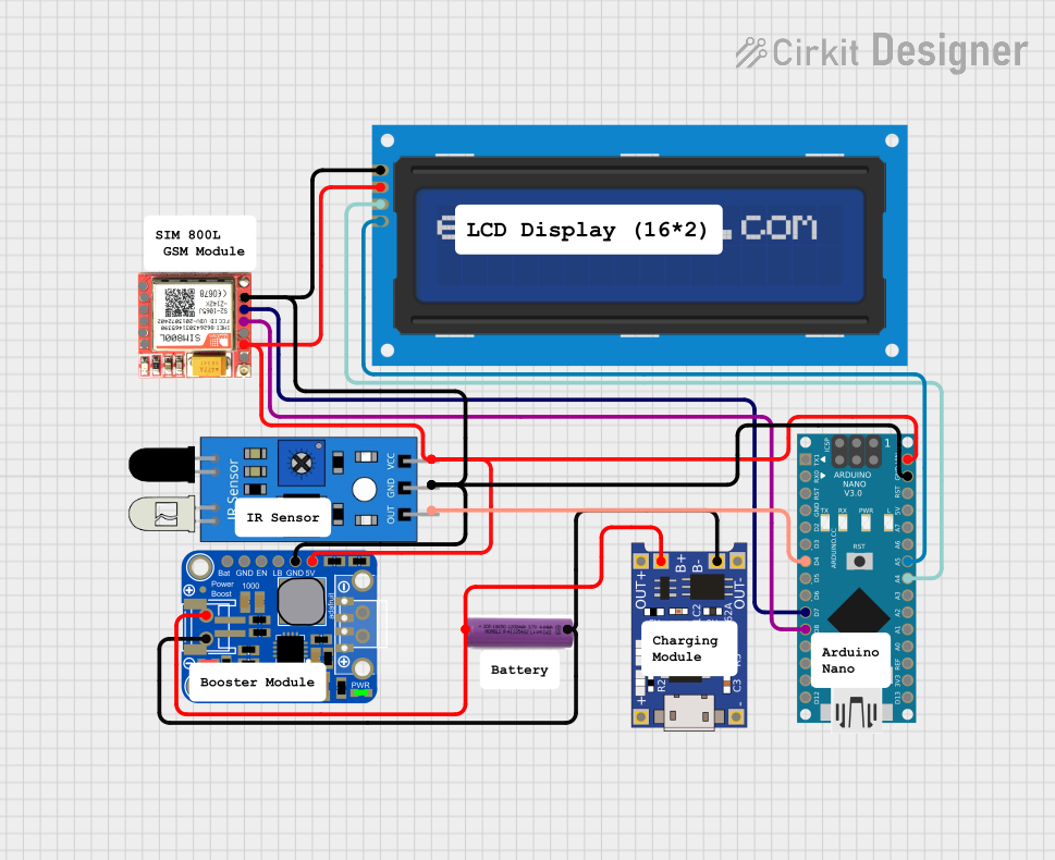
Arduino Nano-Based SMS Alert System with IR Sensor and SIM800L
Image of GSM Based Door Security system: A project utilizing LYPR540AH in a practical application
This circuit is designed to interface an Arduino Nano with an IR sensor for input, a SIM800L module for GSM communication, and an I2C LCD screen for output display. It includes a 3.7V battery with a TP4056 charging module and a PowerBoost 1000 Basic for power management. The Arduino's code is currently a placeholder, suggesting that the user-defined functionality is pending.
Cirkit Designer LogoOpen Project in Cirkit Designer
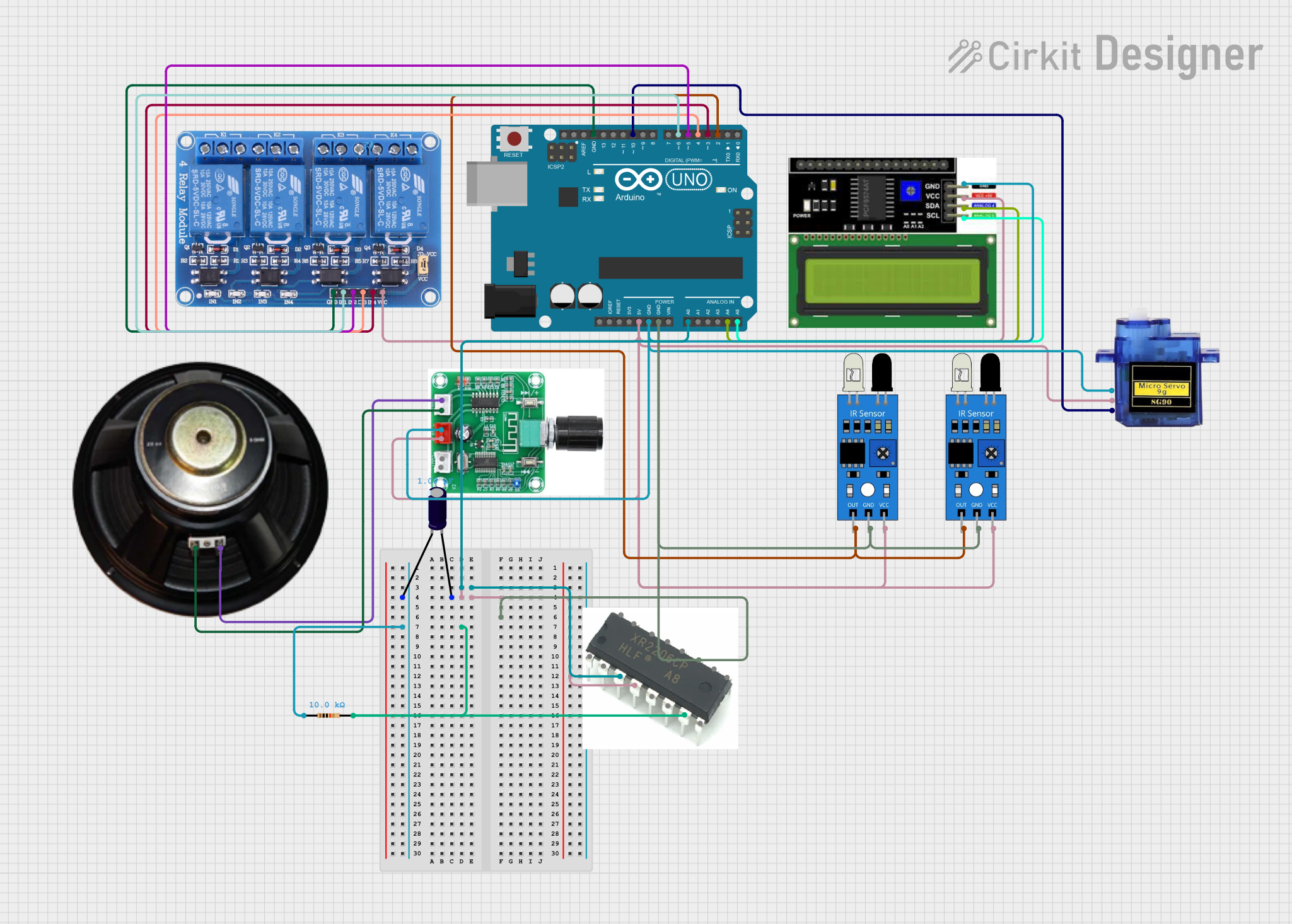
Arduino UNO Controlled Soundwave Generator with IR Sensor Activation and Relay Switching
Image of Fish Attractor: A project utilizing LYPR540AH in a practical application
This circuit features an Arduino UNO microcontroller interfaced with a 4-channel relay, two IR sensors, a servo motor, an LCD I2C display, a PAM8403 audio amplifier connected to a speaker, and an XR2206 function generator with a resistor and capacitor for frequency shaping. The Arduino controls the relays based on a potentiometer input, displays frequency information on the LCD, and adjusts the servo position in response to the IR sensors. The XR2206 generates an adjustable frequency signal, while the PAM8403 amplifies audio for the speaker.
Cirkit Designer LogoOpen Project in Cirkit Designer
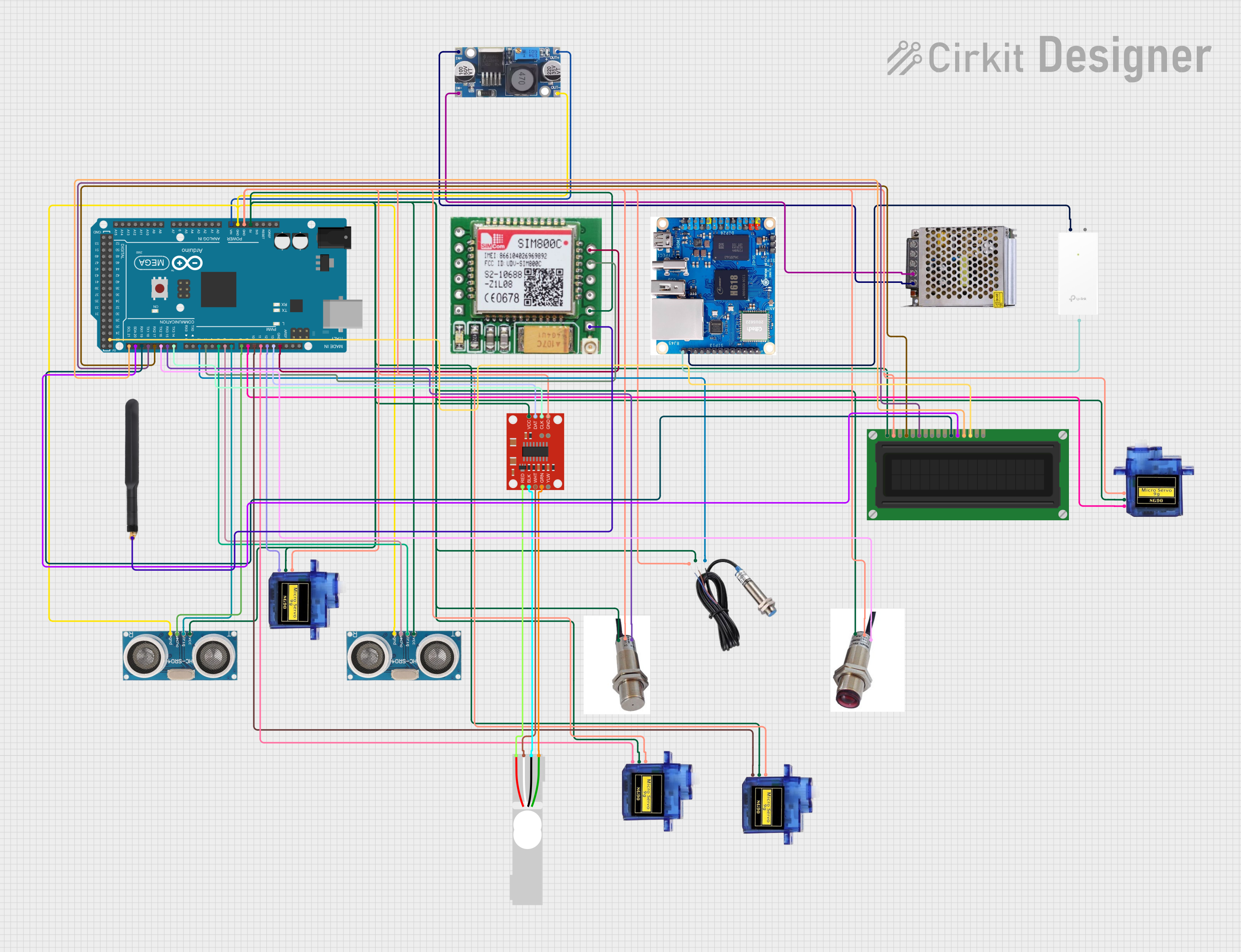
Arduino Mega 2560-Based Reverse Vending Machine with GSM and Wi-Fi Connectivity
Image of RVM WIFI: A project utilizing LYPR540AH in a practical application
This circuit is a reverse vending machine for plastic bottles and cans, utilizing an Arduino Mega 2560 to interface with various sensors and actuators. It includes ultrasonic sensors for distance measurement, a load cell for weight measurement, micro servos for actuation, and a GSM module for communication. The system also features an LCD display for user interaction and uses inductive and photoelectric sensors for object detection.
Cirkit Designer LogoOpen Project in Cirkit Designer

Explore Projects Built with LYPR540AH

Use Cirkit Designer to design, explore, and prototype these projects online. Some projects support real-time simulation. Click "Open Project" to start designing instantly!
Image of Door security system: A project utilizing LYPR540AH in a practical application
Arduino Mega 2560 Based Security System with Fingerprint Authentication and SMS Alerts
This circuit features an Arduino Mega 2560 microcontroller interfaced with a SIM800L GSM module, two fingerprint scanners, an I2C LCD display, an IR sensor, and a piezo buzzer. Power management is handled by a PowerBoost 1000 Basic Pad USB, a TP4056 charging module, and a Li-ion 18650 battery, with an option to use a Mini AC-DC 110V-230V to 5V 700mA module for direct power supply. The primary functionality appears to be a security system with GSM communication capabilities, biometric access control, and visual/audible feedback.
Cirkit Designer LogoOpen Project in Cirkit Designer
Image of GSM Based Door Security system: A project utilizing LYPR540AH in a practical application
Arduino Nano-Based SMS Alert System with IR Sensor and SIM800L
This circuit is designed to interface an Arduino Nano with an IR sensor for input, a SIM800L module for GSM communication, and an I2C LCD screen for output display. It includes a 3.7V battery with a TP4056 charging module and a PowerBoost 1000 Basic for power management. The Arduino's code is currently a placeholder, suggesting that the user-defined functionality is pending.
Cirkit Designer LogoOpen Project in Cirkit Designer
Image of Fish Attractor: A project utilizing LYPR540AH in a practical application
Arduino UNO Controlled Soundwave Generator with IR Sensor Activation and Relay Switching
This circuit features an Arduino UNO microcontroller interfaced with a 4-channel relay, two IR sensors, a servo motor, an LCD I2C display, a PAM8403 audio amplifier connected to a speaker, and an XR2206 function generator with a resistor and capacitor for frequency shaping. The Arduino controls the relays based on a potentiometer input, displays frequency information on the LCD, and adjusts the servo position in response to the IR sensors. The XR2206 generates an adjustable frequency signal, while the PAM8403 amplifies audio for the speaker.
Cirkit Designer LogoOpen Project in Cirkit Designer
Image of RVM WIFI: A project utilizing LYPR540AH in a practical application
Arduino Mega 2560-Based Reverse Vending Machine with GSM and Wi-Fi Connectivity
This circuit is a reverse vending machine for plastic bottles and cans, utilizing an Arduino Mega 2560 to interface with various sensors and actuators. It includes ultrasonic sensors for distance measurement, a load cell for weight measurement, micro servos for actuation, and a GSM module for communication. The system also features an LCD display for user interaction and uses inductive and photoelectric sensors for object detection.
Cirkit Designer LogoOpen Project in Cirkit Designer

Common Applications

  • Robotics for precise arm or joint positioning
  • Industrial automation systems for linear motion control
  • CNC machines and 3D printers for accurate axis feedback
  • Automotive systems for position sensing
  • Medical devices requiring precise linear displacement measurement

Technical Specifications

Key Technical Details

Parameter Value
Supply Voltage 3.3V to 5.5V
Operating Current 10 mA (typical)
Output Signal Type Analog or PWM
Measurement Range 0 to 100 mm
Resolution 0.01 mm
Linearity Error ±0.1% of full scale
Operating Temperature -40°C to +85°C
Housing Material Aluminum alloy
Connector Type 4-pin Molex

Pin Configuration and Descriptions

Pin Number Pin Name Description
1 VCC Power supply input (3.3V to 5.5V)
2 GND Ground connection
3 OUT Output signal (Analog or PWM, depending on mode)
4 MODE Mode selection (Analog: LOW, PWM: HIGH)

Usage Instructions

How to Use the LYPR540AH in a Circuit

  1. Power Supply: Connect the VCC pin to a stable 3.3V or 5V power source and the GND pin to the ground of your circuit.
  2. Output Signal: Depending on your application, configure the MODE pin:
    • Set MODE to LOW for analog output.
    • Set MODE to HIGH for PWM output.
  3. Signal Reading:
    • For analog mode, connect the OUT pin to an ADC (Analog-to-Digital Converter) input on your microcontroller.
    • For PWM mode, connect the OUT pin to a digital input capable of reading PWM signals.
  4. Calibration: Perform a calibration routine to map the sensor's output to the desired range of motion in your application.

Important Considerations and Best Practices

  • Use decoupling capacitors (e.g., 0.1 µF) near the VCC pin to reduce noise and ensure stable operation.
  • Avoid exposing the sensor to excessive mechanical stress or vibrations, as this may affect accuracy.
  • Ensure proper grounding to minimize electrical noise interference.
  • If using PWM mode, verify that your microcontroller can handle the sensor's PWM frequency (typically 1 kHz).

Example Code for Arduino UNO

Below is an example of how to interface the LYPR540AH with an Arduino UNO in analog mode:

// Define the pin connected to the sensor's OUT pin
const int sensorPin = A0; // Analog pin A0 for reading sensor output

void setup() {
  Serial.begin(9600); // Initialize serial communication at 9600 baud
  pinMode(sensorPin, INPUT); // Set the sensor pin as input
}

void loop() {
  int sensorValue = analogRead(sensorPin); // Read the analog value from the sensor
  float position = map(sensorValue, 0, 1023, 0, 100); 
  // Map the sensor value to the measurement range (0 to 100 mm)

  Serial.print("Position: ");
  Serial.print(position); // Print the position value
  Serial.println(" mm"); // Add units for clarity

  delay(100); // Delay for 100 ms before the next reading
}

Notes:

  • If using PWM mode, replace analogRead() with a function to decode PWM signals.
  • Adjust the map() function parameters based on your specific calibration.

Troubleshooting and FAQs

Common Issues and Solutions

  1. No Output Signal:

    • Verify that the sensor is powered correctly (check VCC and GND connections).
    • Ensure the MODE pin is set to the desired mode (LOW for analog, HIGH for PWM).
  2. Inaccurate Readings:

    • Check for proper calibration of the sensor.
    • Ensure there is no mechanical obstruction or misalignment in the sensor's mounting.
  3. Noisy Output:

    • Add a decoupling capacitor near the sensor's power pins.
    • Ensure proper grounding and minimize electrical noise in the circuit.
  4. PWM Signal Not Detected:

    • Verify that the microcontroller's digital input pin supports PWM decoding.
    • Check the MODE pin configuration and ensure it is set to HIGH for PWM mode.

FAQs

Q: Can the LYPR540AH be used in outdoor environments?
A: Yes, the sensor is designed to operate in a wide temperature range (-40°C to +85°C). However, ensure it is protected from direct exposure to water or extreme environmental conditions.

Q: How do I switch between analog and PWM modes?
A: Use the MODE pin to select the desired mode. Set it to LOW for analog output or HIGH for PWM output.

Q: What is the maximum cable length for connecting the sensor?
A: For optimal performance, keep the cable length under 1 meter. Use shielded cables for longer distances to reduce noise.

Q: Can I use the LYPR540AH with a 3.3V microcontroller?
A: Yes, the sensor operates within a supply voltage range of 3.3V to 5.5V, making it compatible with 3.3V systems.

By following this documentation, users can effectively integrate the LYPR540AH into their projects and achieve precise linear position sensing.