How to Use 4071: Examples, Pinouts, and Specs

 Design with 4071 in Cirkit Designer
Introduction
The 4071 IC is a fundamental component in digital electronics, featuring a quad 2-input OR gate. This integrated circuit is used to perform logical OR operations, which are essential in various digital systems. The OR gate is a digital logic gate that outputs a high (logic 1) if any of its inputs are high. The 4071 IC is commonly used in applications such as logic function generation, signal gating, and circuit design for computational logic.
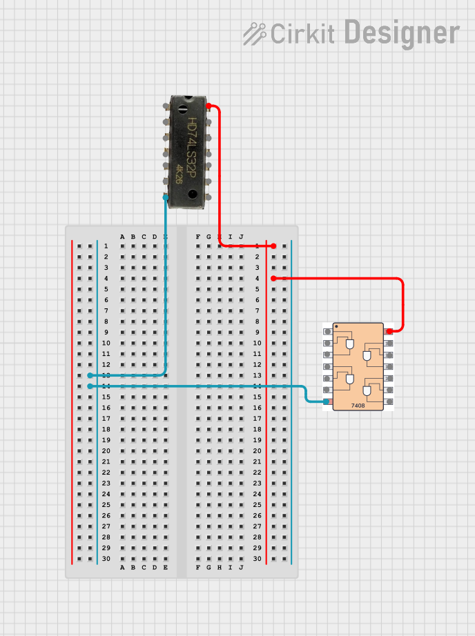
Explore Projects Built with 4071

 Open Project in Cirkit Designer
 Open Project in Cirkit Designer
 Open Project in Cirkit Designer
 Open Project in Cirkit Designer
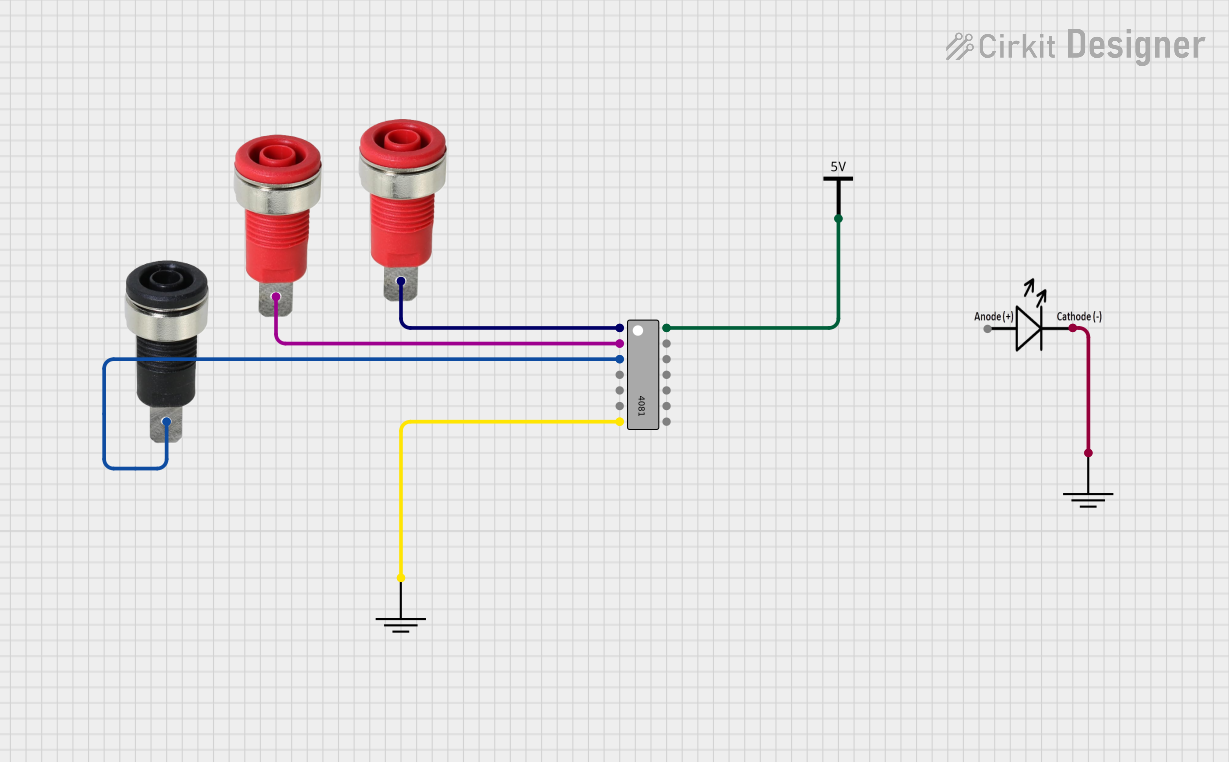
Explore Projects Built with 4071

 Open Project in Cirkit Designer
 Open Project in Cirkit Designer
 Open Project in Cirkit Designer
 Open Project in Cirkit Designer
Common Applications and Use Cases
- Digital logic circuits
- Signal processing
- Control systems
- Alarm systems
- Function generators
Technical Specifications
Key Technical Details
- Supply Voltage (Vcc): 3V to 18V
- Input Voltage (Vin): -0.5V to Vcc+0.5V
- Output Voltage (Vout): 0V to Vcc
- Operating Temperature: -55°C to +125°C
- Current per Output Pin: 2 mA to 25 mA (depending on Vcc)
- Propagation Delay Time: Typically 60 ns (at Vcc = 10V, Ta = 25°C)
Pin Configuration and Descriptions
| Pin Number | Name | Description |
|---|---|---|
| 1 | A1 | First input of the first OR gate |
| 2 | B1 | Second input of the first OR gate |
| 3 | Y1 | Output of the first OR gate |
| 4 | A2 | First input of the second OR gate |
| 5 | B2 | Second input of the second OR gate |
| 6 | Y2 | Output of the second OR gate |
| 7 | GND | Ground (0V) |
| 8 | Y3 | Output of the third OR gate |
| 9 | B3 | Second input of the third OR gate |
| 10 | A3 | First input of the third OR gate |
| 11 | Y4 | Output of the fourth OR gate |
| 12 | B4 | Second input of the fourth OR gate |
| 13 | A4 | First input of the fourth OR gate |
| 14 | Vcc | Positive supply voltage |
Usage Instructions
How to Use the 4071 in a Circuit
- Connect the Vcc pin (14) to the positive supply voltage within the range of 3V to 18V.
- Connect the GND pin (7) to the ground of the power supply.
- Apply input signals to the A and B pins of the OR gates you intend to use.
- The corresponding Y pins will output the OR operation result of the inputs.
Important Considerations and Best Practices
- Ensure that the supply voltage does not exceed the recommended maximum to prevent damage.
- Inputs should not be left floating; they should be connected to a definite high or low logic level.
- Decoupling capacitors (typically 0.1 µF) should be placed close to the Vcc pin to filter out noise.
- Avoid loading the output beyond the specified current rating to maintain proper logic levels.
Troubleshooting and FAQs
Common Issues
- Outputs not functioning as expected: Verify that all inputs are connected correctly and that the supply voltage is within the specified range.
- IC overheating: Check if the supply voltage is too high or if the output is short-circuited.
Solutions and Tips for Troubleshooting
- Double-check the wiring and ensure that the IC is not inserted backward in the socket.
- Measure the supply voltage with a multimeter to ensure it is within the specified range.
- If the IC is overheating, immediately disconnect the power and inspect for shorts or incorrect connections.
FAQs
Q: Can I replace a 4071 IC with another OR gate IC? A: Yes, as long as the replacement IC has the same pin configuration and can handle the same voltage and current levels.
Q: What happens if I apply a voltage higher than 18V to the Vcc pin? A: Applying a voltage higher than the maximum rated Vcc can permanently damage the IC.
Q: Is it possible to cascade multiple 4071 ICs to create larger OR functions? A: Yes, you can connect the outputs of several 4071 ICs to the inputs of another to create OR functions with more inputs.
Example Code for Arduino UNO
The following is an example of how to use the 4071 OR gate with an Arduino UNO. This code will demonstrate a simple OR operation with two inputs and one output.
// Define the Arduino pins connected to the 4071 inputs and output
const int inputPinA = 2; // Connect to A1 on the 4071
const int inputPinB = 3; // Connect to B1 on the 4071
const int outputPin = 4; // Connect to Y1 on the 4071

void setup() {
  // Configure the input and output pins
  pinMode(inputPinA, OUTPUT);
  pinMode(inputPinB, OUTPUT);
  pinMode(outputPin, INPUT);
}

void loop() {
  // Set both inputs to LOW and read the output
  digitalWrite(inputPinA, LOW);
  digitalWrite(inputPinB, LOW);
  Serial.print("Output with both inputs LOW: ");
  Serial.println(digitalRead(outputPin));

  // Set input A to HIGH and read the output
  digitalWrite(inputPinA, HIGH);
  digitalWrite(inputPinB, LOW);
  Serial.print("Output with input A HIGH: ");
  Serial.println(digitalRead(outputPin));

  // Set input B to HIGH and read the output
  digitalWrite(inputPinA, LOW);
  digitalWrite(inputPinB, HIGH);
  Serial.print("Output with input B HIGH: ");
  Serial.println(digitalRead(outputPin));

  // Set both inputs to HIGH and read the output
  digitalWrite(inputPinA, HIGH);
  digitalWrite(inputPinB, HIGH);
  Serial.print("Output with both inputs HIGH: ");
  Serial.println(digitalRead(outputPin));

  // Wait for a second before repeating the loop
  delay(1000);
}
Remember to connect the 4071 Vcc and GND pins to the Arduino 5V and GND, respectively, and ensure that the inputs and outputs are connected as defined in the code.