
How to Use 3296: Examples, Pinouts, and Specs
 Design with 3296 in Cirkit Designer
Introduction
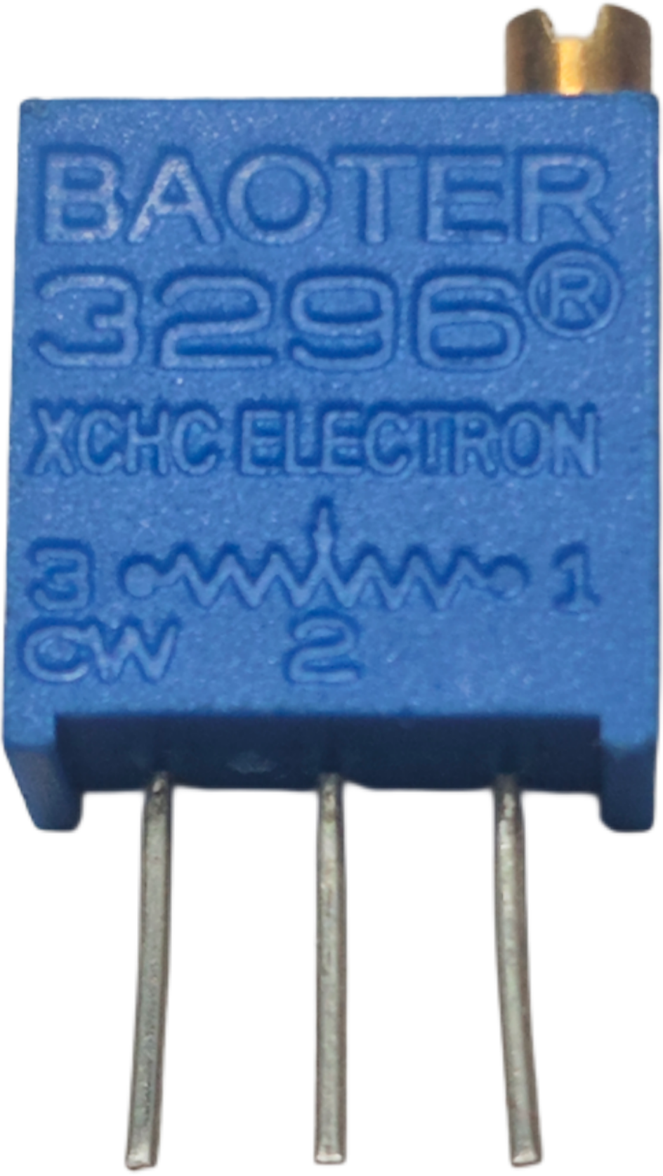
The 3296 is a multi-turn trimmer potentiometer designed for precise resistance adjustments in electronic circuits. Its multi-turn mechanism allows for fine-tuning, making it ideal for applications requiring high accuracy and stability. The 3296 is commonly used in calibration, tuning, and signal conditioning circuits, as well as in devices like power supplies, amplifiers, and sensors.
Explore Projects Built with 3296
 Open Project in Cirkit Designer
 Open Project in Cirkit Designer
 Open Project in Cirkit Designer
 Open Project in Cirkit Designer
Explore Projects Built with 3296
Open Project in Cirkit DesignerOpen Project in Cirkit DesignerOpen Project in Cirkit DesignerOpen Project in Cirkit DesignerTechnical Specifications
The 3296 trimmer potentiometer is available in various resistance values and configurations. Below are its key technical details:
- Resistance Range: 100 Ω to 1 MΩ (varies by model)
- Tolerance: ±10% (typical)
- Power Rating: 0.5 W (at 70°C)
- Temperature Coefficient: ±100 ppm/°C
- Adjustment Turns: 25 turns (multi-turn)
- Operating Temperature Range: -55°C to +125°C
- Maximum Voltage: 200 V (or as specified by the resistance value)
- Mounting Type: Through-hole or surface-mount (depending on model)
Pin Configuration and Descriptions
The 3296 has three pins, which are typically arranged in a straight line. The pin configuration is as follows:
| Pin Number | Name | Description |
|---|---|---|
| 1 | Terminal 1 | One end of the resistive element. |
| 2 | Wiper | Adjustable contact that moves along the resistive element to vary resistance. |
| 3 | Terminal 2 | The other end of the resistive element. |
Pin Layout Diagram
   1   2   3
   |---|---|
   |   |   |
Usage Instructions
How to Use the 3296 in a Circuit
- Determine the Resistance Value: Select the appropriate 3296 model based on the required resistance range for your application.
- Connect the Pins:
- Connect Pin 1 and Pin 3 across the circuit where the resistance is to be adjusted.
- Use Pin 2 (the wiper) to tap into the desired resistance value.
- Adjust the Resistance:
- Use a small screwdriver to turn the adjustment screw on the top of the 3296.
- Rotate clockwise to increase resistance or counterclockwise to decrease resistance.
- Verify the Adjustment:
- Measure the resistance using a multimeter to ensure the desired value is achieved.
Important Considerations and Best Practices
- Avoid Over-Tightening: Do not force the adjustment screw beyond its limits, as this may damage the component.
- Power Dissipation: Ensure the power dissipation does not exceed the rated 0.5 W to prevent overheating.
- Mounting: Secure the 3296 firmly on the PCB to avoid mechanical stress during operation.
- Environmental Conditions: Use the component within its specified temperature range for optimal performance.
Example: Using the 3296 with an Arduino UNO
The 3296 can be used to adjust the input voltage to an Arduino analog pin. Below is an example circuit and code:
Circuit Setup
- Connect Pin 1 of the 3296 to 5V.
- Connect Pin 3 to GND.
- Connect Pin 2 (wiper) to Arduino's analog input pin (e.g., A0).
Arduino Code
// Example code to read the resistance value from a 3296 trimmer potentiometer
// connected to analog pin A0 on an Arduino UNO.

const int potPin = A0; // Define the analog pin connected to the 3296 wiper

void setup() {
  Serial.begin(9600); // Initialize serial communication at 9600 baud
}

void loop() {
  int potValue = analogRead(potPin); // Read the analog value (0-1023)

  // Convert the analog value to a voltage (assuming 5V reference)
  float voltage = potValue * (5.0 / 1023.0);

  // Print the voltage to the Serial Monitor
  Serial.print("Voltage: ");
  Serial.print(voltage);
  Serial.println(" V");

  delay(500); // Wait for 500 ms before the next reading
}
Troubleshooting and FAQs
Common Issues
No Change in Resistance:
- Cause: The adjustment screw may not be turned properly.
- Solution: Use a precision screwdriver and ensure the screw is rotated within its range.
Component Overheating:
- Cause: Exceeding the power rating of 0.5 W.
- Solution: Reduce the current or voltage applied to the component.
Inconsistent Readings:
- Cause: Poor soldering or loose connections.
- Solution: Inspect and re-solder the connections if necessary.
Wiper Not Functioning:
- Cause: Internal damage to the wiper mechanism.
- Solution: Replace the 3296 with a new component.
FAQs
Q1: Can the 3296 be used for high-frequency applications?
A1: The 3296 is not specifically designed for high-frequency circuits. For such applications, consider components with lower parasitic inductance and capacitance.
Q2: How many adjustment cycles can the 3296 withstand?
A2: The 3296 is rated for approximately 200 adjustment cycles, depending on usage conditions.
Q3: Can I use the 3296 in a surface-mount design?
A3: Yes, surface-mount versions of the 3296 are available. Ensure you select the correct model for your PCB design.
Q4: What tools are recommended for adjusting the 3296?
A4: Use a small, non-conductive precision screwdriver to avoid damaging the adjustment screw or causing short circuits.
By following this documentation, you can effectively integrate the 3296 trimmer potentiometer into your electronic projects for precise resistance adjustments.