Cirkit Designer
Your all-in-one circuit design IDE
Home /
Component Documentation
How to Use MYOSA Motherboard: Examples, Pinouts, and Specs
Introduction
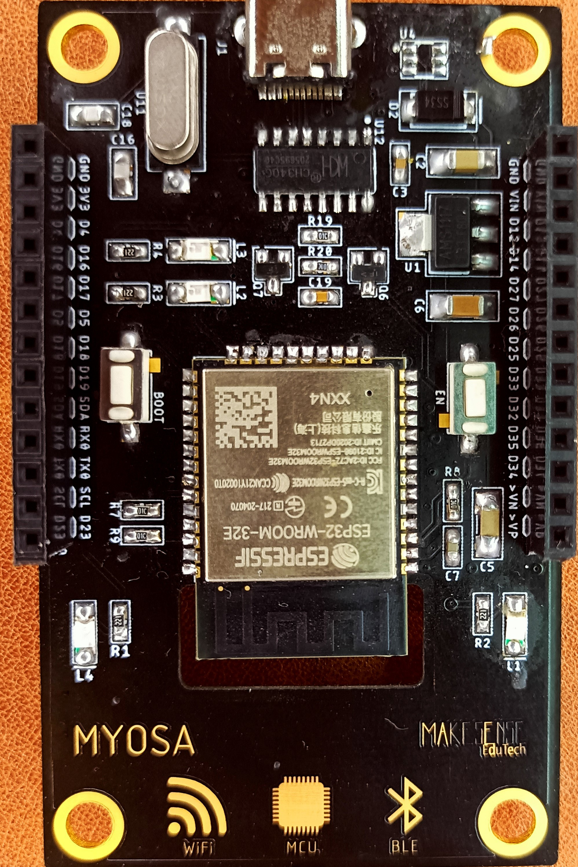
The MYOSA Motherboard (ESP 32) is a central printed circuit board (PCB) designed to facilitate communication between various computer components, including the CPU, RAM, and other hardware peripherals. This versatile motherboard is ideal for a wide range of applications, from embedded systems to IoT projects, due to its robust performance and extensive connectivity options.
Explore Projects Built with MYOSA Motherboard
Arduino UNO Controlled Robotic Arm with Myoware Muscle Sensor and Battery Power
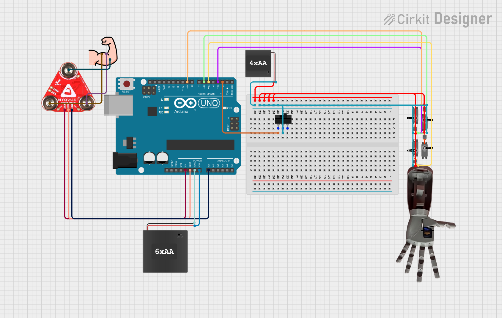
This circuit is a muscle-controlled robotic arm system. It uses a Myoware 2.0 Muscle Sensor to detect muscle activity, which is processed by an Arduino UNO to control four servos that move the arm. Power is supplied by 6xAA and 4xAA battery packs, with a toggle switch to control the power to the servos.
Arduino Uno R3 and Myoware Muscle Sensor Interface
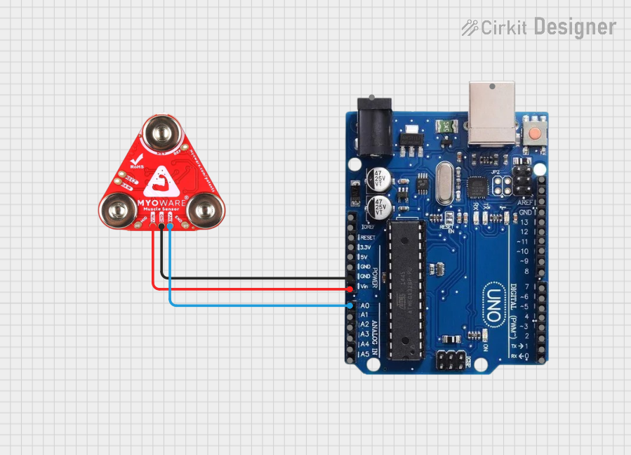
This circuit connects an Arduino Uno R3 with a Myoware 2.0 Muscle Sensor. The Arduino is configured to provide power to the Myoware sensor and to read the sensor's analog voltage output corresponding to muscle activity from the ENV pin through the Arduino's A0 analog input. The purpose of this circuit is to monitor and process muscle activity signals for applications such as prosthetics control or gesture recognition.
Wi-Fi Controlled Servo Motor with MyoWare Muscle Sensor and Arduino
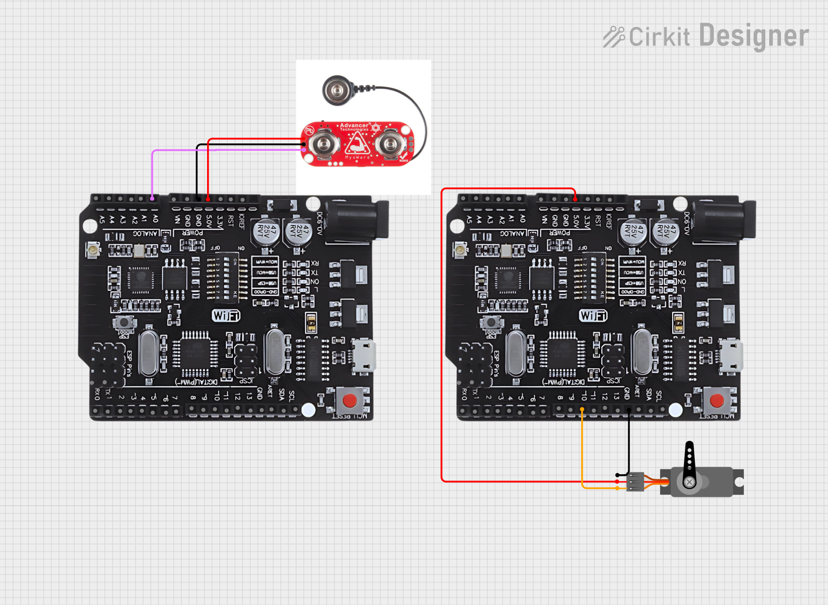
This circuit uses an Arduino UNO with WiFi to read muscle activity data from a MyoWare Muscle Sensor and control a servo motor based on the sensor input. The Arduino reads the sensor data, processes it, and sends the data over WiFi to another Arduino for further actions.
Arduino Mega 2560-Based Smart Home Control System with LCD Display and Flame Sensor

This circuit is a multi-functional embedded system featuring an Arduino Mega 2560 microcontroller that interfaces with a 4x4 membrane keypad, a 20x4 I2C LCD, an 8x8 LED matrix, a DS3231 RTC module, a passive buzzer, and a KY-026 flame sensor. The system is powered by a 5V PSU and is designed to provide real-time clock functionality, user input via the keypad, visual output on the LCD and LED matrix, and flame detection with an audible alert.
Explore Projects Built with MYOSA Motherboard
Arduino UNO Controlled Robotic Arm with Myoware Muscle Sensor and Battery Power
This circuit is a muscle-controlled robotic arm system. It uses a Myoware 2.0 Muscle Sensor to detect muscle activity, which is processed by an Arduino UNO to control four servos that move the arm. Power is supplied by 6xAA and 4xAA battery packs, with a toggle switch to control the power to the servos.
Arduino Uno R3 and Myoware Muscle Sensor Interface
This circuit connects an Arduino Uno R3 with a Myoware 2.0 Muscle Sensor. The Arduino is configured to provide power to the Myoware sensor and to read the sensor's analog voltage output corresponding to muscle activity from the ENV pin through the Arduino's A0 analog input. The purpose of this circuit is to monitor and process muscle activity signals for applications such as prosthetics control or gesture recognition.
Wi-Fi Controlled Servo Motor with MyoWare Muscle Sensor and Arduino
This circuit uses an Arduino UNO with WiFi to read muscle activity data from a MyoWare Muscle Sensor and control a servo motor based on the sensor input. The Arduino reads the sensor data, processes it, and sends the data over WiFi to another Arduino for further actions.
Arduino Mega 2560-Based Smart Home Control System with LCD Display and Flame Sensor
This circuit is a multi-functional embedded system featuring an Arduino Mega 2560 microcontroller that interfaces with a 4x4 membrane keypad, a 20x4 I2C LCD, an 8x8 LED matrix, a DS3231 RTC module, a passive buzzer, and a KY-026 flame sensor. The system is powered by a 5V PSU and is designed to provide real-time clock functionality, user input via the keypad, visual output on the LCD and LED matrix, and flame detection with an audible alert.
Common Applications and Use Cases
- Embedded Systems: Ideal for integrating various sensors and actuators.
- IoT Projects: Suitable for smart home devices, wearables, and other IoT applications.
- Prototyping: Excellent for rapid development and testing of new hardware and software solutions.
- Educational Purposes: Perfect for learning about computer architecture and electronics.
Technical Specifications
Key Technical Details
| Specification | Value |
|---|---|
| Manufacturer | MYOSA |
| Part ID | ESP 32 |
| CPU | Dual-core 32-bit LX6 microprocessor |
| Clock Speed | Up to 240 MHz |
| RAM | 520 KB SRAM |
| Flash Memory | 4 MB |
| Operating Voltage | 3.3V |
| Input Voltage | 5V (via USB) |
| Digital I/O Pins | 34 |
| Analog Input Pins | 18 |
| Communication | Wi-Fi, Bluetooth |
| Power Consumption | 160 mA (average) |
Pin Configuration and Descriptions
| Pin Number | Pin Name | Description |
|---|---|---|
| 1 | GND | Ground |
| 2 | 3V3 | 3.3V Power Output |
| 3 | EN | Enable Pin |
| 4 | IO0 | GPIO 0, used for boot mode selection |
| 5 | IO1 | GPIO 1, UART0 TXD |
| 6 | IO2 | GPIO 2, ADC2_CH2 |
| 7 | IO3 | GPIO 3, UART0 RXD |
| 8 | IO4 | GPIO 4, ADC2_CH0 |
| 9 | IO5 | GPIO 5, ADC2_CH1 |
| 10 | IO6 | GPIO 6, Flash SCK |
| ... | ... | ... |
| 34 | IO34 | GPIO 34, ADC1_CH6 |
Usage Instructions
How to Use the Component in a Circuit
Powering the Board:
- Connect the 5V input to the USB port or use the 3.3V pin for direct power supply.
Connecting Peripherals:
- Use the digital I/O pins to connect sensors, actuators, and other peripherals.
- Analog input pins can be used for reading sensor data.
Programming:
- The ESP 32 can be programmed using the Arduino IDE or other compatible environments.
- Ensure the correct board and port are selected in the IDE.
Important Considerations and Best Practices
- Power Supply: Ensure a stable power supply to avoid unexpected resets or malfunctions.
- Pin Usage: Be mindful of the pin functions to avoid conflicts, especially with GPIO pins that have multiple functions.
- Heat Management: The ESP 32 can get warm during operation; consider adding a heat sink for prolonged use.
Sample Arduino Code
// Sample code to blink an LED connected to GPIO 2

void setup() {
  // Initialize the digital pin as an output.
  pinMode(2, OUTPUT);
}

void loop() {
  // Turn the LED on (HIGH is the voltage level)
  digitalWrite(2, HIGH);
  delay(1000); // Wait for a second

  // Turn the LED off by making the voltage LOW
  digitalWrite(2, LOW);
  delay(1000); // Wait for a second
}
Troubleshooting and FAQs
Common Issues Users Might Face
Board Not Detected:
- Ensure the USB cable is properly connected.
- Check if the correct board and port are selected in the IDE.
Upload Failures:
- Press and hold the "BOOT" button while uploading the code.
- Ensure the correct drivers are installed.
Unstable Operation:
- Verify the power supply is stable and sufficient.
- Check for any loose connections or short circuits.
Solutions and Tips for Troubleshooting
Resetting the Board:
- Press the "EN" button to reset the board if it becomes unresponsive.
Serial Monitor:
- Use the Serial Monitor in the Arduino IDE to debug and view output messages.
Firmware Updates:
- Ensure the ESP 32 firmware is up to date for optimal performance and compatibility.
By following this documentation, users can effectively utilize the MYOSA Motherboard (ESP 32) in their projects, ensuring reliable performance and ease of use.