How to Use M12-5P-Female: Examples, Pinouts, and Specs
Introduction
The M12-5P-Female is a 5-pin female connector widely used in industrial applications for connecting sensors, actuators, and other devices. Its robust design ensures reliable performance in harsh environments, making it ideal for use in automation systems, robotics, and industrial machinery. The connector's threaded coupling mechanism provides a secure and vibration-resistant connection, while its compact size allows for easy integration into tight spaces.
Explore Projects Built with M12-5P-Female


Explore Projects Built with M12-5P-Female
Common Applications and Use Cases
- Industrial automation systems
- Robotics and motion control
- Sensor and actuator connections
- Process control and monitoring
- Harsh environment applications requiring secure and durable connections
Technical Specifications
The M12-5P-Female connector is designed to meet industrial standards for durability and performance. Below are its key technical details:
General Specifications
- Connector Type: M12, 5-pin, female
- Rated Voltage: 60V AC/DC
- Rated Current: 4A per pin
- Contact Resistance: ≤ 5 mΩ
- Insulation Resistance: ≥ 100 MΩ
- Operating Temperature Range: -25°C to +85°C
- Ingress Protection (IP) Rating: IP67 (when mated)
- Material:
- Housing: Nickel-plated brass or stainless steel
- Contacts: Gold-plated brass
- Sealing: NBR or silicone
Pin Configuration and Descriptions
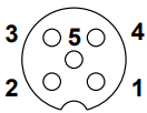
The M12-5P-Female connector has five pins arranged in a circular pattern. The pinout is as follows:
| Pin Number | Signal | Description |
|---|---|---|
| 1 | V+ | Positive supply voltage |
| 2 | Signal 1 (S1) | Signal or data line 1 |
| 3 | V- (GND) | Ground or negative supply voltage |
| 4 | Signal 2 (S2) | Signal or data line 2 |
| 5 | Shield/PE | Protective earth or shield |
Usage Instructions
How to Use the M12-5P-Female Connector in a Circuit
Wiring the Connector:
- Identify the pinout of the connector using the table above.
- Solder or crimp the wires to the corresponding pins based on your application.
- Ensure proper insulation and strain relief for the wires to prevent damage.
Mating the Connector:
- Align the male and female connectors using the keying mechanism.
- Gently push the connectors together and rotate the threaded coupling nut clockwise until it is fully tightened. This ensures a secure and vibration-resistant connection.
Connecting to a Device:
- Use the connector to interface with sensors, actuators, or other devices.
- Verify the voltage and current ratings of the connected devices to ensure compatibility.
Important Considerations and Best Practices
- Environmental Protection: Ensure the connector is properly mated to maintain its IP67 rating, protecting it from dust and water ingress.
- Cable Selection: Use cables with appropriate shielding and insulation to minimize electrical noise and ensure reliable signal transmission.
- Avoid Over-Tightening: Do not overtighten the coupling nut, as this may damage the threads or compromise the seal.
- Polarity Check: Double-check the wiring to avoid reverse polarity, which could damage connected devices.
Example: Connecting to an Arduino UNO
The M12-5P-Female connector can be used to interface sensors with an Arduino UNO. Below is an example of connecting a sensor with a digital output to the Arduino:
Circuit Diagram
- Pin 1 (V+): Connect to the Arduino's 5V pin.
- Pin 3 (V-): Connect to the Arduino's GND pin.
- Pin 2 (S1): Connect to a digital input pin on the Arduino (e.g., D2).
Arduino Code Example
// Example code for reading a digital sensor connected via M12-5P-Female connector
const int sensorPin = 2; // Pin connected to Signal 1 (S1) of the sensor
int sensorValue = 0;     // Variable to store the sensor state

void setup() {
  pinMode(sensorPin, INPUT); // Set the sensor pin as an input
  Serial.begin(9600);        // Initialize serial communication
}

void loop() {
  sensorValue = digitalRead(sensorPin); // Read the sensor state
  Serial.print("Sensor State: ");
  Serial.println(sensorValue);         // Print the sensor state to the Serial Monitor
  delay(500);                          // Wait for 500ms before the next reading
}
Troubleshooting and FAQs
Common Issues and Solutions
Loose Connection:
- Issue: The connector feels loose or disconnects under vibration.
- Solution: Ensure the coupling nut is fully tightened. Check for damage to the threads or keying mechanism.
Signal Interference:
- Issue: Unstable or noisy signals from the connected device.
- Solution: Use shielded cables and connect the shield (Pin 5) to ground to reduce electrical noise.
Water or Dust Ingress:
- Issue: The connector fails in wet or dusty environments.
- Solution: Verify that the connector is properly mated and the sealing is intact. Replace damaged seals if necessary.
Incorrect Wiring:
- Issue: The connected device does not function as expected.
- Solution: Double-check the wiring against the pinout table. Ensure correct polarity and signal connections.
FAQs
Q1: Can the M12-5P-Female connector handle high currents?
A1: The connector is rated for a maximum current of 4A per pin. For higher currents, consider using a connector with a higher current rating.
Q2: Is the connector compatible with all M12 male connectors?
A2: The M12-5P-Female connector is compatible with M12 male connectors that have the same 5-pin configuration and keying.
Q3: How do I clean the connector?
A3: Use a soft, dry cloth to clean the connector. Avoid using abrasive materials or solvents that could damage the contacts or housing.
Q4: Can I use the connector in outdoor applications?
A4: Yes, the connector is suitable for outdoor use when properly mated, as it provides IP67 protection against dust and water ingress.