How to Use PNP Transistor: Examples, Pinouts, and Specs

Introduction
A PNP transistor is a type of bipolar junction transistor (BJT) that allows current to flow from the emitter to the collector when the base is pulled low (i.e., when the base voltage is lower than the emitter voltage). It is widely used in electronic circuits for switching and amplification purposes. Unlike its counterpart, the NPN transistor, the PNP transistor is activated by a negative base current relative to the emitter.
Explore Projects Built with PNP Transistor

Explore Projects Built with PNP Transistor
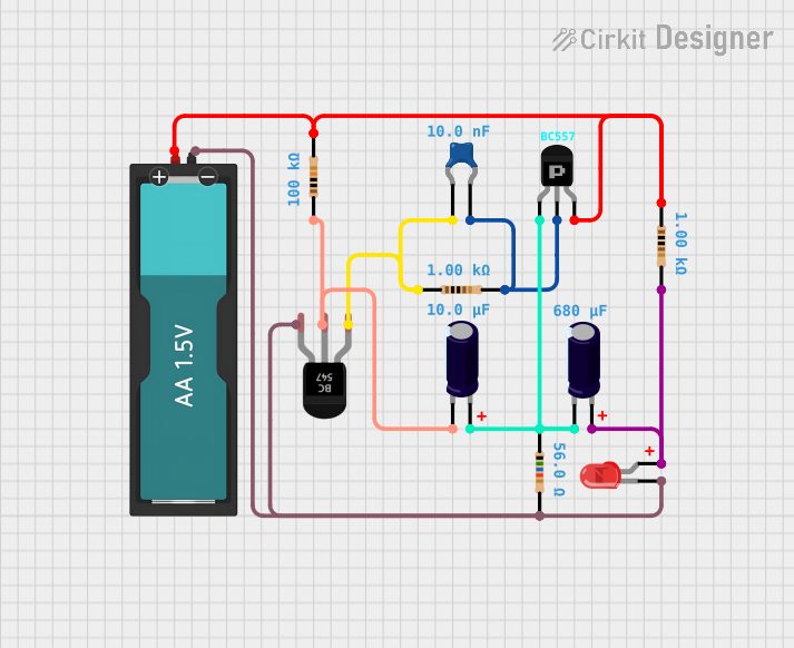
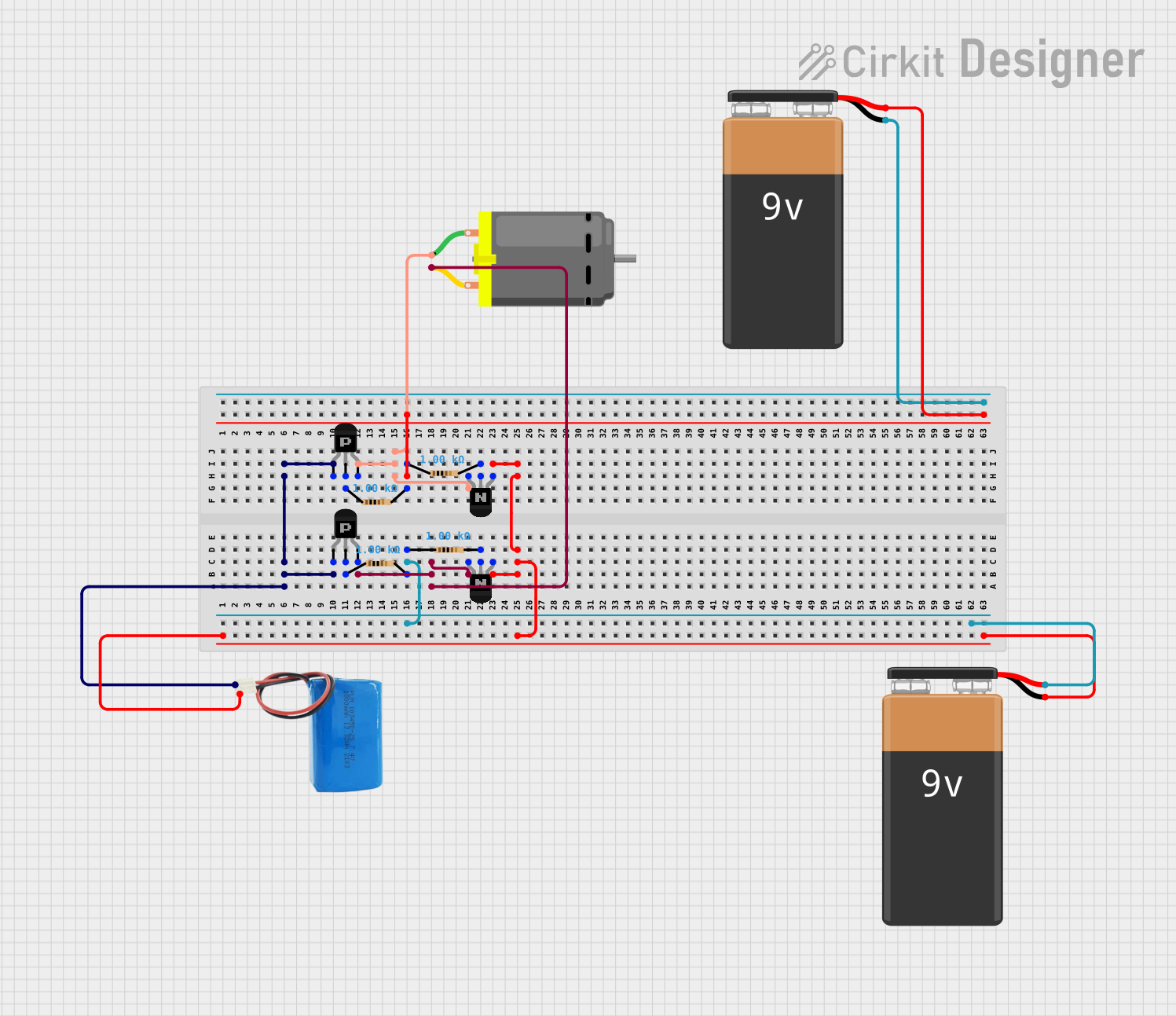
Common Applications and Use Cases
- Amplification of analog signals in audio and RF circuits
- Switching low-current loads in electronic devices
- Used in complementary push-pull amplifier configurations
- Current regulation and voltage control in power supplies
Technical Specifications
Below are the general technical specifications for a standard PNP transistor (e.g., 2N2907). Always refer to the specific datasheet of the transistor you are using for precise details.
Key Technical Details
- Type: Bipolar Junction Transistor (PNP)
- Maximum Collector-Emitter Voltage (VCEO): 40V
- Maximum Collector-Base Voltage (VCBO): 60V
- Maximum Emitter-Base Voltage (VEBO): 5V
- Maximum Collector Current (IC): 600mA
- Power Dissipation (PD): 400mW
- DC Current Gain (hFE): 100 to 300 (varies by model)
- Transition Frequency (fT): 200 MHz (typical)
Pin Configuration and Descriptions
The PNP transistor typically has three pins: Emitter (E), Base (B), and Collector (C). The pinout may vary depending on the package type (e.g., TO-92, TO-220). Below is the pin configuration for a common TO-92 package.
| Pin Number | Name | Description |
|---|---|---|
| 1 | Emitter (E) | Current flows out of this pin |
| 2 | Base (B) | Controls the transistor's operation (input) |
| 3 | Collector (C) | Current flows into this pin (output) |
Usage Instructions
How to Use the Component in a Circuit
- Biasing the Transistor: To turn on a PNP transistor, the base voltage must be lower than the emitter voltage (typically by 0.6V to 0.7V for silicon transistors). For example, if the emitter is at 5V, the base should be at approximately 4.3V or lower.
- Connecting the Load: The load (e.g., a resistor, LED, or motor) is typically connected between the collector and the positive supply voltage.
- Base Resistor: Use a resistor in series with the base to limit the base current and prevent damage to the transistor. The resistor value can be calculated using Ohm's law:
[ R_B = \frac{V_{in} - V_{BE}}{I_B} ]
where ( V_{in} ) is the input voltage, ( V_{BE} ) is the base-emitter voltage (typically 0.6V), and ( I_B ) is the desired base current.
Example Circuit with Arduino UNO
Below is an example of using a PNP transistor to control an LED with an Arduino UNO.
Circuit Description
- The emitter is connected to the 5V supply.
- The collector is connected to one terminal of the LED, with the other terminal connected to ground via a current-limiting resistor.
- The base is connected to an Arduino digital pin through a base resistor.
Arduino Code
// Define the pin connected to the base of the PNP transistor
const int transistorBasePin = 9;

void setup() {
  pinMode(transistorBasePin, OUTPUT); // Set the pin as an output
}

void loop() {
  // Turn the LED ON by pulling the base HIGH (transistor OFF)
  digitalWrite(transistorBasePin, HIGH);
  delay(1000); // Wait for 1 second

  // Turn the LED OFF by pulling the base LOW (transistor ON)
  digitalWrite(transistorBasePin, LOW);
  delay(1000); // Wait for 1 second
}
Important Considerations and Best Practices
- Polarity: Ensure correct polarity when connecting the transistor. Reversing the emitter and collector can damage the component.
- Base Resistor: Always use a base resistor to limit the base current.
- Power Dissipation: Ensure the transistor does not exceed its maximum power dissipation rating. Use a heatsink if necessary.
- Voltage Ratings: Do not exceed the maximum voltage ratings for VCEO, VCBO, or VEBO.
Troubleshooting and FAQs
Common Issues Users Might Face
Transistor Not Switching:
- Check if the base voltage is sufficiently lower than the emitter voltage.
- Verify the base resistor value to ensure adequate base current.
- Ensure the load is properly connected between the collector and the positive supply.
Excessive Heat:
- Verify that the transistor is not exceeding its maximum power dissipation.
- Check for short circuits or excessive current through the collector.
No Current Flow Through the Load:
- Ensure the load is properly connected and functional.
- Verify that the transistor is not damaged by testing it with a multimeter.
Solutions and Tips for Troubleshooting
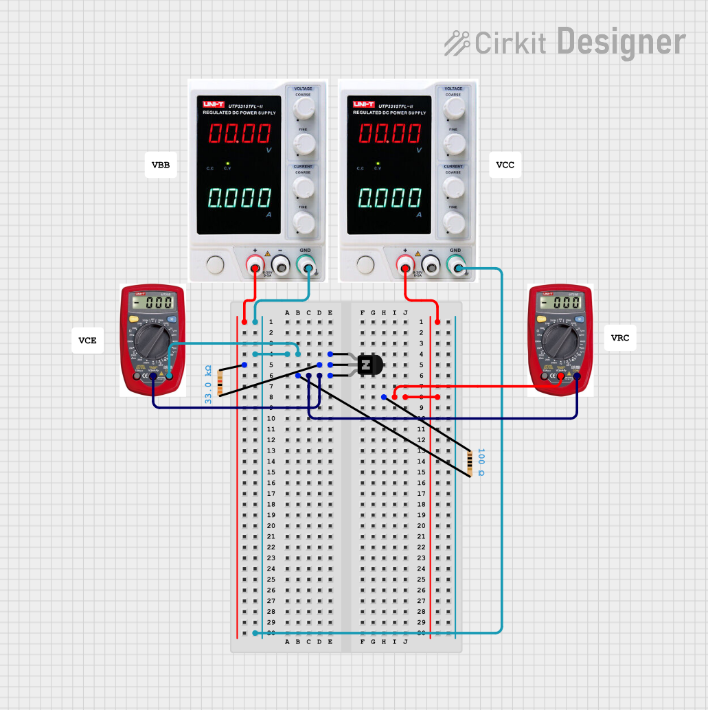
- Use a multimeter to check the transistor's pinout and verify its functionality. In diode mode, test the base-emitter and base-collector junctions for proper forward and reverse bias behavior.
- Double-check all connections in the circuit to ensure they match the schematic.
- If the transistor is not functioning as expected, replace it with a new one to rule out component failure.
By following these guidelines, you can effectively use a PNP transistor in your electronic projects for switching and amplification tasks.