How to Use AC MCB (Blue): Examples, Pinouts, and Specs
Introduction
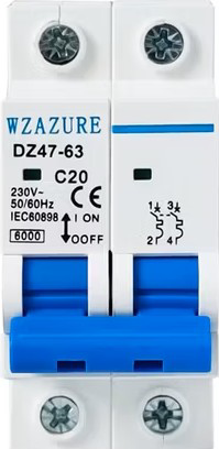
The AC Miniature Circuit Breaker (MCB) is a compact, electromechanical device designed to protect electrical circuits from overloads and short circuits. This specific model features a distinctive blue casing, making it easily identifiable in electrical panels. It is widely used in residential, commercial, and industrial applications to ensure the safety and reliability of electrical systems.
Explore Projects Built with AC MCB (Blue)


Explore Projects Built with AC MCB (Blue)
Common Applications and Use Cases
- Protection of household electrical circuits (e.g., lighting, outlets)
- Industrial machinery and equipment safety
- Commercial building electrical distribution systems
- Renewable energy systems (e.g., solar inverters)
- Temporary power setups for events or construction sites
Technical Specifications
Key Technical Details
- Rated Voltage: 230/400V AC
- Rated Current: 6A, 10A, 16A, 20A, 32A, 40A (varies by model)
- Breaking Capacity: 6kA (6000A)
- Tripping Curve: Type B, C, or D (depending on application)
- Frequency: 50/60 Hz
- Number of Poles: 1P, 2P, 3P, or 4P
- Operating Temperature: -5°C to +40°C
- Casing Material: Flame-retardant thermoplastic (blue color)
- Mounting: DIN rail (35mm standard)
- Standards Compliance: IEC/EN 60898-1
Pin Configuration and Descriptions
The AC MCB does not have traditional "pins" like an IC but instead features terminal connections for input and output wiring. Below is a description of the terminals:
| Terminal Name | Description | Connection Type |
|---|---|---|
| Line (L) In | Input terminal for live wire | Screw terminal |
| Line (L) Out | Output terminal for live wire | Screw terminal |
| Neutral (N) In | Input terminal for neutral wire (optional, for 2P+) | Screw terminal |
| Neutral (N) Out | Output terminal for neutral wire (optional, for 2P+) | Screw terminal |
Note: For single-pole (1P) MCBs, only the Line (L) terminals are used. For multi-pole (2P, 3P, 4P) MCBs, both Line and Neutral terminals are available.
Usage Instructions
How to Use the Component in a Circuit
- Select the Correct MCB: Choose an MCB with the appropriate current rating and tripping curve for your application. For example:
- Type B: Suitable for residential circuits with low inrush currents (e.g., lighting).
- Type C: Ideal for circuits with moderate inrush currents (e.g., motors).
- Type D: Used for industrial circuits with high inrush currents (e.g., transformers).
- Mount the MCB: Securely attach the MCB to a standard 35mm DIN rail in the distribution panel.
- Connect the Wires:
- Connect the live wire to the Line (L) In terminal.
- Connect the load side live wire to the Line (L) Out terminal.
- For multi-pole MCBs, connect the neutral wires to the Neutral (N) terminals as needed.
- Tighten the Terminals: Use a screwdriver to ensure all terminal screws are securely fastened. Loose connections can cause overheating.
- Power On: Switch the MCB to the "ON" position to energize the circuit.
Important Considerations and Best Practices
- Do Not Exceed Rated Current: Ensure the connected load does not exceed the MCB's rated current to avoid nuisance tripping.
- Check Compatibility: Verify that the MCB's voltage and frequency ratings match your electrical system.
- Regular Maintenance: Periodically inspect the MCB for signs of wear, damage, or loose connections.
- Avoid Overheating: Ensure proper ventilation around the MCB to prevent overheating.
- Use Proper Tools: Always use insulated tools when working with electrical components.
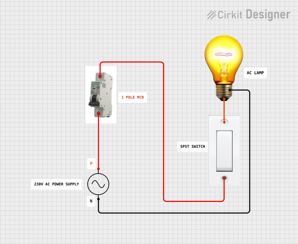
Example: Connecting an MCB to an Arduino-Controlled Circuit
While MCBs are not directly connected to microcontrollers like Arduino, they can be used to protect circuits powered by an Arduino. Below is an example of how to integrate an MCB into a simple Arduino-controlled lighting circuit:
// Example: Arduino-controlled lighting circuit with MCB protection
// Note: The MCB is used to protect the AC side of the circuit.
// Ensure proper isolation between AC and DC components.

void setup() {
  pinMode(13, OUTPUT); // Set pin 13 as output for controlling a relay
}

void loop() {
  digitalWrite(13, HIGH); // Turn on the relay (activates AC load)
  delay(5000);            // Keep the load on for 5 seconds
  digitalWrite(13, LOW);  // Turn off the relay
  delay(5000);            // Wait for 5 seconds before repeating
}

// Important: Use an optocoupler or relay module to safely interface
// the Arduino with the AC circuit. The MCB should be installed on
// the live wire to protect the AC load from overload or short circuits.
Troubleshooting and FAQs
Common Issues Users Might Face
MCB Trips Frequently:
- Cause: Overloaded circuit or short circuit.
- Solution: Reduce the load on the circuit or check for wiring faults.
MCB Does Not Trip During a Fault:
- Cause: Faulty MCB or incorrect current rating.
- Solution: Replace the MCB with a properly rated one and test its functionality.
Loose Connections:
- Cause: Improperly tightened terminal screws.
- Solution: Re-tighten all terminal screws securely.
Overheating of MCB:
- Cause: High ambient temperature or poor ventilation.
- Solution: Improve ventilation around the MCB and ensure it is operating within its temperature range.
Solutions and Tips for Troubleshooting
- Use a multimeter to check for continuity and proper voltage levels in the circuit.
- Inspect the MCB for physical damage, such as cracks or burn marks.
- Test the MCB by simulating an overload condition (e.g., using a test load) to verify its tripping mechanism.
- Consult the manufacturer's datasheet for detailed specifications and troubleshooting guidelines.
By following this documentation, users can effectively utilize the AC MCB (Blue) to protect their electrical systems and ensure safe operation.