
How to Use esp: Examples, Pinouts, and Specs
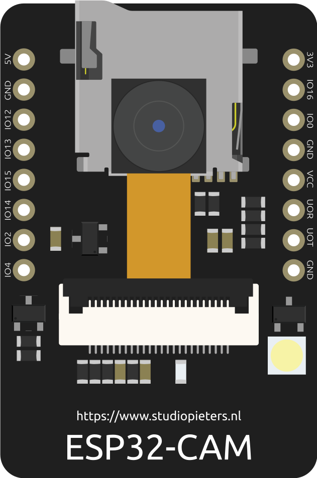
 Design with esp in Cirkit Designer
Introduction
The ESP series, developed by Espressif Systems, is a family of low-cost, low-power system-on-chip (SoC) microcontrollers. These devices are equipped with integrated Wi-Fi and Bluetooth capabilities, making them ideal for Internet of Things (IoT) applications. The ESP series is widely used for smart home devices, wearable electronics, industrial automation, and other wireless communication projects. Popular models include the ESP8266 and ESP32, which offer varying levels of performance and features to suit different use cases.
Common applications of ESP microcontrollers include:
- Home automation systems (e.g., smart lights, thermostats)
- Wireless sensor networks
- IoT-enabled appliances
- Remote monitoring and control systems
- Prototyping and educational projects
Explore Projects Built with esp
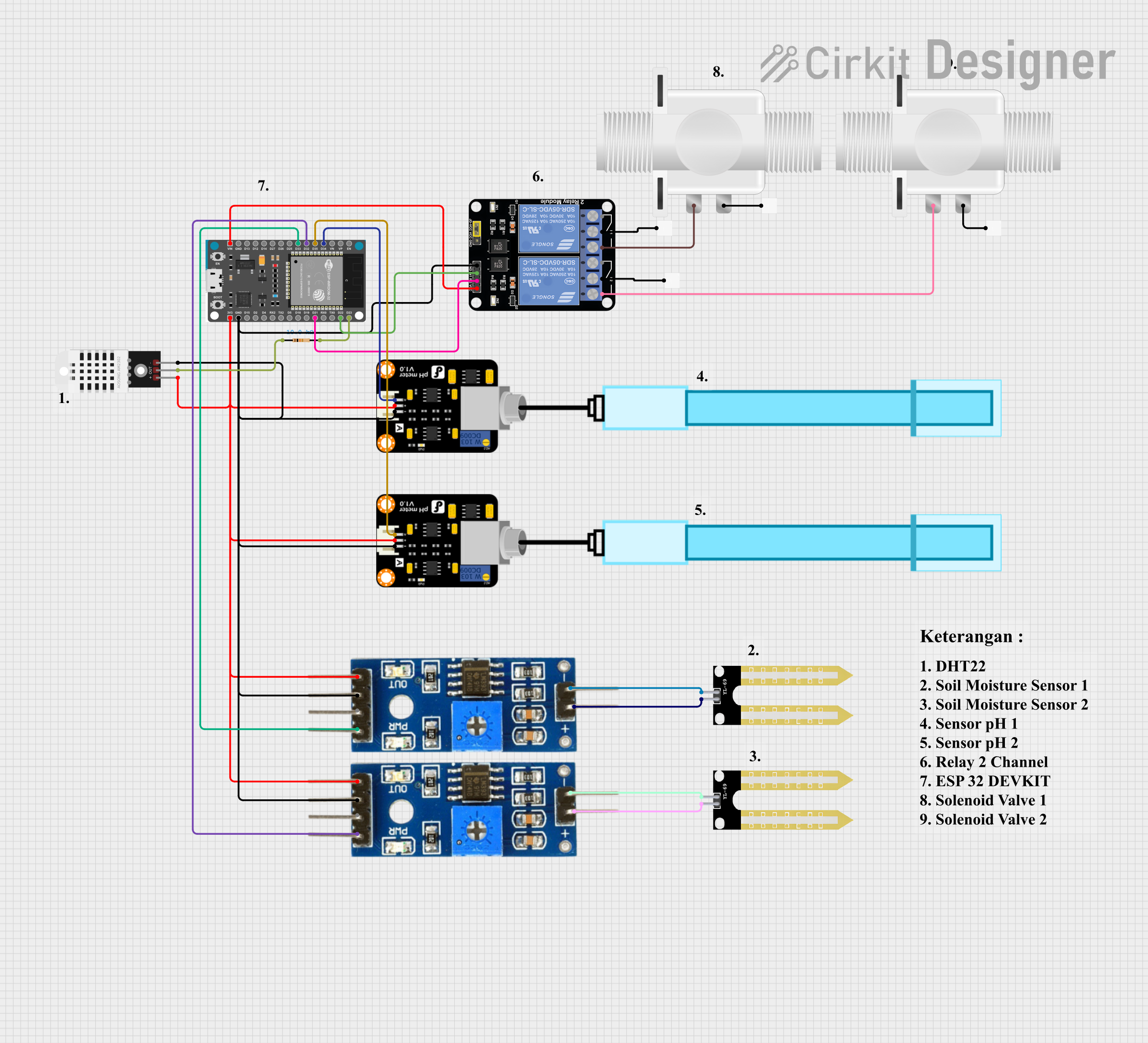 Open Project in Cirkit Designer
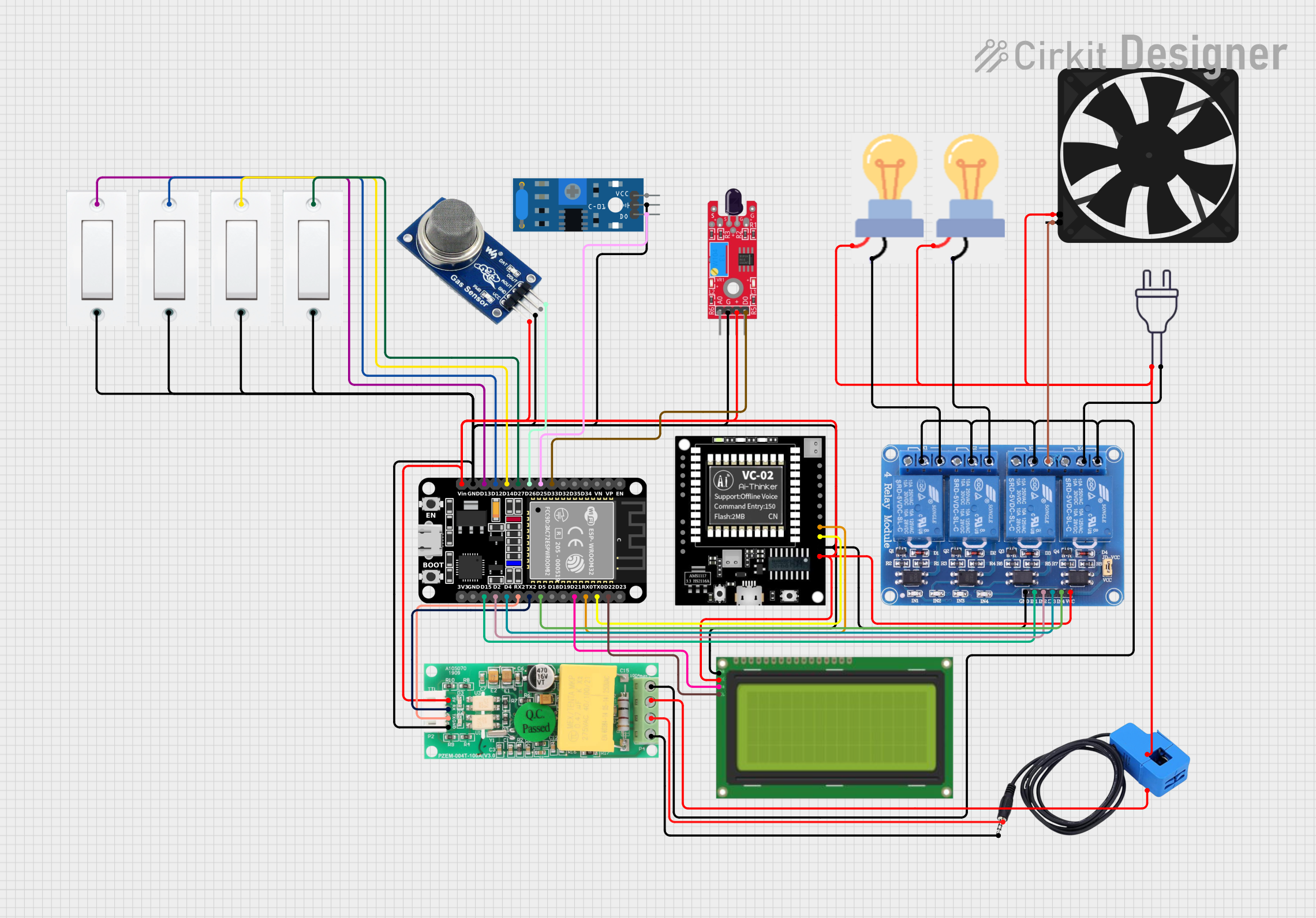 Open Project in Cirkit Designer
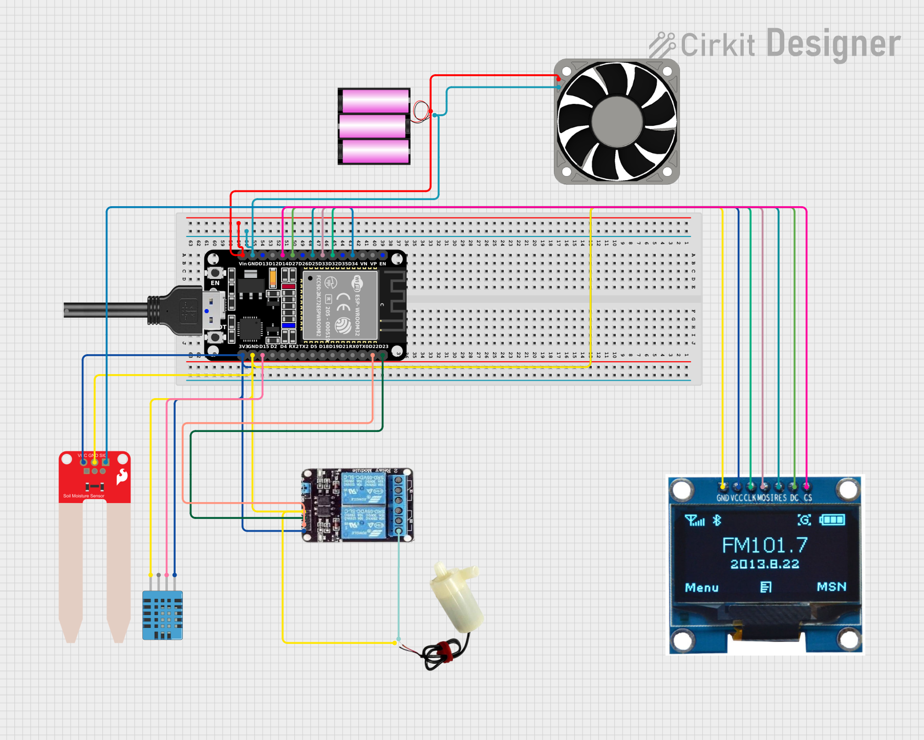 Open Project in Cirkit Designer
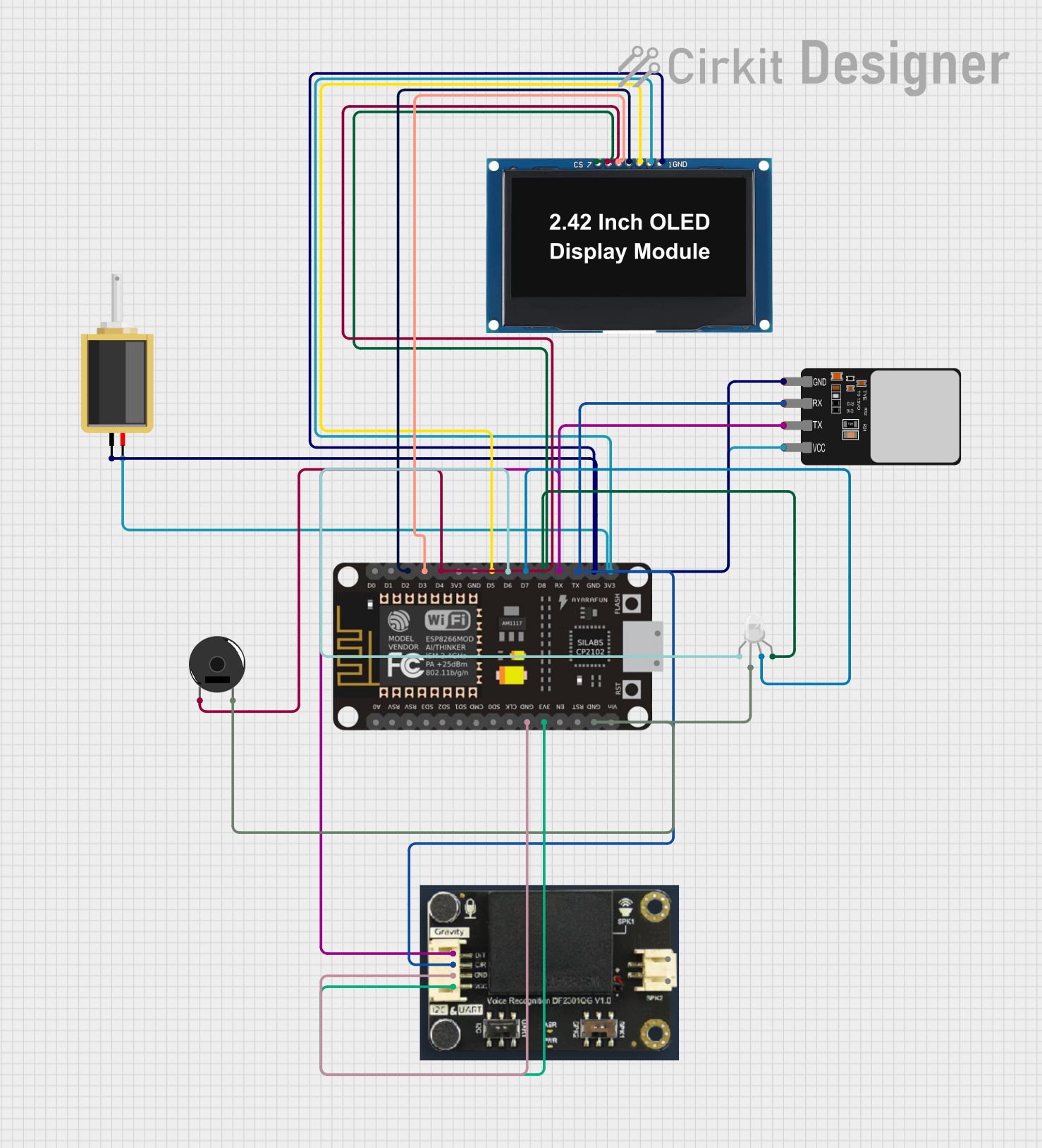 Open Project in Cirkit Designer
Explore Projects Built with esp
Open Project in Cirkit DesignerOpen Project in Cirkit DesignerOpen Project in Cirkit DesignerOpen Project in Cirkit DesignerTechnical Specifications
Below are the general technical specifications for the ESP series. Note that specific models (e.g., ESP8266, ESP32) may have slight variations.
General Specifications
- Processor: Tensilica Xtensa LX6 (ESP32) or LX106 (ESP8266)
- Clock Speed: Up to 240 MHz (ESP32) / 80 MHz (ESP8266)
- Wi-Fi: IEEE 802.11 b/g/n
- Bluetooth: Bluetooth 4.2 and BLE (ESP32 only)
- Operating Voltage: 3.0V to 3.6V
- GPIO Pins: Varies by model (ESP32: up to 36, ESP8266: up to 17)
- Flash Memory: 512 KB to 16 MB (varies by model)
- Power Consumption: Ultra-low power modes available
- Interfaces: UART, SPI, I2C, PWM, ADC, DAC (ESP32 only)
Pin Configuration and Descriptions
ESP8266 Pinout
| Pin Name | Function | Description |
|---|---|---|
| VCC | Power Supply | Connect to 3.3V |
| GND | Ground | Connect to ground |
| GPIO0 | General Purpose I/O | Used for boot mode selection or I/O |
| GPIO2 | General Purpose I/O | Default high during boot |
| GPIO15 | General Purpose I/O | Default low during boot |
| RX | UART Receive | Serial data input |
| TX | UART Transmit | Serial data output |
| CH_PD | Chip Enable | Must be pulled high to enable the chip |
| RST | Reset | Active low reset pin |
ESP32 Pinout
| Pin Name | Function | Description |
|---|---|---|
| VIN | Power Supply | Connect to 5V (regulated to 3.3V internally) |
| GND | Ground | Connect to ground |
| GPIO0 | General Purpose I/O | Used for boot mode selection or I/O |
| GPIO2 | General Purpose I/O | Default high during boot |
| GPIO36 | ADC Input | Analog input pin |
| GPIO39 | ADC Input | Analog input pin |
| EN | Enable | Must be pulled high to enable the chip |
| TX0 | UART Transmit | Serial data output |
| RX0 | UART Receive | Serial data input |
Usage Instructions
How to Use the ESP in a Circuit
- Power Supply: Ensure the ESP is powered with a stable 3.3V supply. For ESP32, you can use the VIN pin with a 5V input.
- Boot Mode: For ESP8266, connect GPIO0 to GND during boot to enter programming mode. For ESP32, this is handled automatically by most development boards.
- Connections: Use UART pins (TX/RX) for serial communication with a computer or microcontroller. Connect GPIO pins as needed for sensors, actuators, or other peripherals.
- Programming: Use the Arduino IDE, Espressif's ESP-IDF, or other compatible tools to upload code to the ESP.
Example Code for Arduino UNO with ESP8266
Below is an example of using an ESP8266 to connect to a Wi-Fi network and send data to a server.
#include <ESP8266WiFi.h> // Include the ESP8266 Wi-Fi library

const char* ssid = "Your_SSID";       // Replace with your Wi-Fi network name
const char* password = "Your_Password"; // Replace with your Wi-Fi password

void setup() {
  Serial.begin(115200); // Initialize serial communication at 115200 baud
  WiFi.begin(ssid, password); // Connect to Wi-Fi network

  Serial.print("Connecting to Wi-Fi");
  while (WiFi.status() != WL_CONNECTED) {
    delay(500); // Wait for connection
    Serial.print(".");
  }
  Serial.println("\nConnected to Wi-Fi!");
  Serial.print("IP Address: ");
  Serial.println(WiFi.localIP()); // Print the device's IP address
}

void loop() {
  // Add your main code here
}
Important Considerations and Best Practices
- Voltage Levels: Ensure all GPIO pins operate at 3.3V logic levels. Use level shifters if interfacing with 5V devices.
- Power Supply: Use a stable power source with sufficient current (at least 500 mA for ESP8266, 1A for ESP32).
- Antenna Placement: Avoid placing the ESP near metal objects or inside enclosures that block Wi-Fi signals.
- Firmware Updates: Keep the firmware updated to ensure compatibility and security.
Troubleshooting and FAQs
Common Issues
- ESP Not Connecting to Wi-Fi
- Solution: Double-check the SSID and password. Ensure the router is within range and supports 2.4 GHz Wi-Fi (ESP does not support 5 GHz).
- ESP Not Responding
- Solution: Verify the power supply voltage and current. Ensure the CH_PD (ESP8266) or EN (ESP32) pin is pulled high.
- Upload Fails
- Solution: For ESP8266, ensure GPIO0 is connected to GND during programming. For ESP32, check the USB cable and drivers.
FAQs
Can I use the ESP with a 5V microcontroller? Yes, but you must use level shifters to convert 5V signals to 3.3V for the ESP's GPIO pins.
What is the maximum range of the ESP's Wi-Fi? The range depends on the environment but is typically around 30-50 meters indoors and up to 100 meters outdoors.
Can the ESP run on batteries? Yes, the ESP can run on batteries, but you should use deep sleep modes to conserve power.
By following this documentation, you can effectively integrate ESP microcontrollers into your projects and troubleshoot common issues.