How to Use Thermal Overload Relay (TOR): Examples, Pinouts, and Specs
Introduction
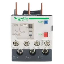
A Thermal Overload Relay (TOR) is a protective device designed to safeguard electric motors from overheating caused by excessive current. It operates by interrupting the power supply to the motor when an overload condition is detected, preventing potential damage to the motor and associated equipment. TORs are widely used in industrial and commercial applications where electric motors are critical to operations.
Explore Projects Built with Thermal Overload Relay (TOR)


Explore Projects Built with Thermal Overload Relay (TOR)
Common Applications and Use Cases
- Protection of electric motors in industrial machinery
- HVAC systems to prevent motor burnout
- Conveyor systems and pumps
- Compressors and fans
- Any application requiring motor overload protection
Technical Specifications
Below are the key technical details and pin configuration for a typical Thermal Overload Relay:
Key Technical Details
| Parameter | Value/Range |
|---|---|
| Rated Operational Voltage | 230V AC to 690V AC |
| Current Range | 0.1A to 630A (varies by model) |
| Trip Class | Class 10, 20, or 30 |
| Reset Mode | Manual or Automatic |
| Contact Configuration | Normally Closed (NC) and Normally Open (NO) |
| Operating Temperature Range | -20°C to +60°C |
| Mounting Type | Direct mounting on contactors or standalone |
Pin Configuration and Descriptions
| Pin/Terminal Label | Description |
|---|---|
| L1, L2, L3 | Input terminals for the three-phase power supply |
| T1, T2, T3 | Output terminals connected to the motor |
| NC | Normally Closed contact for control circuit |
| NO | Normally Open contact for control circuit |
| RESET | Reset button to restore operation after a trip |
| TEST | Test button to simulate an overload condition |
Usage Instructions
How to Use the Component in a Circuit
Wiring the TOR:
- Connect the three-phase power supply to the input terminals (L1, L2, L3).
- Connect the motor leads to the output terminals (T1, T2, T3).
- Integrate the NC and NO contacts into the control circuit for signaling or interlocking purposes.
- Ensure proper grounding of the relay as per the manufacturer's guidelines.
Adjusting the Current Setting:
- Set the overload relay's current adjustment dial to match the full-load current rating of the motor.
- Refer to the motor's nameplate for the correct current rating.
Testing the Relay:
- Use the TEST button to simulate an overload condition and verify the relay's operation.
- Ensure the relay trips and interrupts the circuit as expected.
Resetting After a Trip:
- If the relay trips due to an overload, allow the motor to cool down.
- Press the RESET button to restore the relay to its normal operating state.
Important Considerations and Best Practices
- Always select a TOR with a current range that matches the motor's full-load current.
- Ensure proper ventilation around the relay to prevent overheating.
- Periodically test the relay to ensure it functions correctly.
- Use the manual reset mode in critical applications to prevent automatic restarts after a trip.
- For motors controlled by an Arduino or other microcontrollers, use the relay's NO/NC contacts to monitor or control the motor's status.
Example Arduino Code for Monitoring TOR Status
The following code demonstrates how to monitor the status of a TOR using its NC contact and an Arduino UNO:
// Define the pin connected to the TOR's NC contact
const int torPin = 2; // Digital pin 2

void setup() {
  pinMode(torPin, INPUT_PULLUP); // Set pin as input with pull-up resistor
  Serial.begin(9600); // Initialize serial communication
}

void loop() {
  int torStatus = digitalRead(torPin); // Read the TOR status

  if (torStatus == HIGH) {
    // If the NC contact is open, the relay has tripped
    Serial.println("Thermal Overload Relay TRIPPED! Motor is OFF.");
  } else {
    // If the NC contact is closed, the relay is in normal operation
    Serial.println("Thermal Overload Relay is NORMAL. Motor is ON.");
  }

  delay(1000); // Wait for 1 second before checking again
}
Troubleshooting and FAQs
Common Issues and Solutions
| Issue | Possible Cause | Solution |
|---|---|---|
| Relay does not trip during overload | Incorrect current setting | Adjust the current setting to match the motor's full-load current. |
| Frequent tripping | Motor is overloaded or faulty | Check the motor for mechanical issues or reduce the load. |
| Relay does not reset | Motor has not cooled down or reset mode is incorrect | Allow the motor to cool or switch to manual reset mode. |
| Test button does not work | Faulty relay or improper wiring | Verify wiring and test the relay with a multimeter. |
FAQs
Can a TOR protect against short circuits?
- No, a TOR is designed to protect against overload conditions, not short circuits. Use a circuit breaker or fuse for short-circuit protection.
What is the difference between manual and automatic reset modes?
- In manual reset mode, the relay must be manually reset after a trip. In automatic reset mode, the relay resets itself once the motor cools down.
How often should I test the TOR?
- It is recommended to test the TOR at least once every six months to ensure proper operation.
Can I use a TOR with a single-phase motor?
- Yes, but ensure the TOR is compatible with single-phase operation and wired correctly.
By following this documentation, users can effectively integrate and maintain a Thermal Overload Relay in their motor protection systems.