How to Use Orange Pi: Examples, Pinouts, and Specs
Introduction
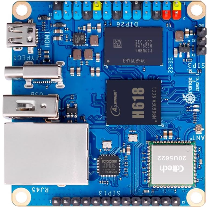
The Orange Pi Zero 3, manufactured by Orange Pi, is a compact and versatile single-board computer (SBC) designed for a wide range of applications. It is particularly well-suited for projects such as media centers, robotics, IoT devices, and lightweight server applications. With its powerful processing capabilities, extensive connectivity options, and support for multiple operating systems, the Orange Pi Zero 3 is an excellent choice for both hobbyists and professionals.
Explore Projects Built with Orange Pi
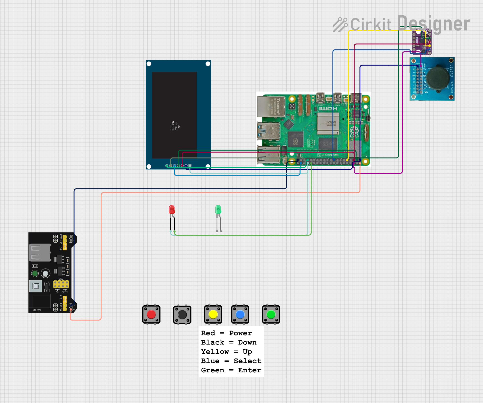
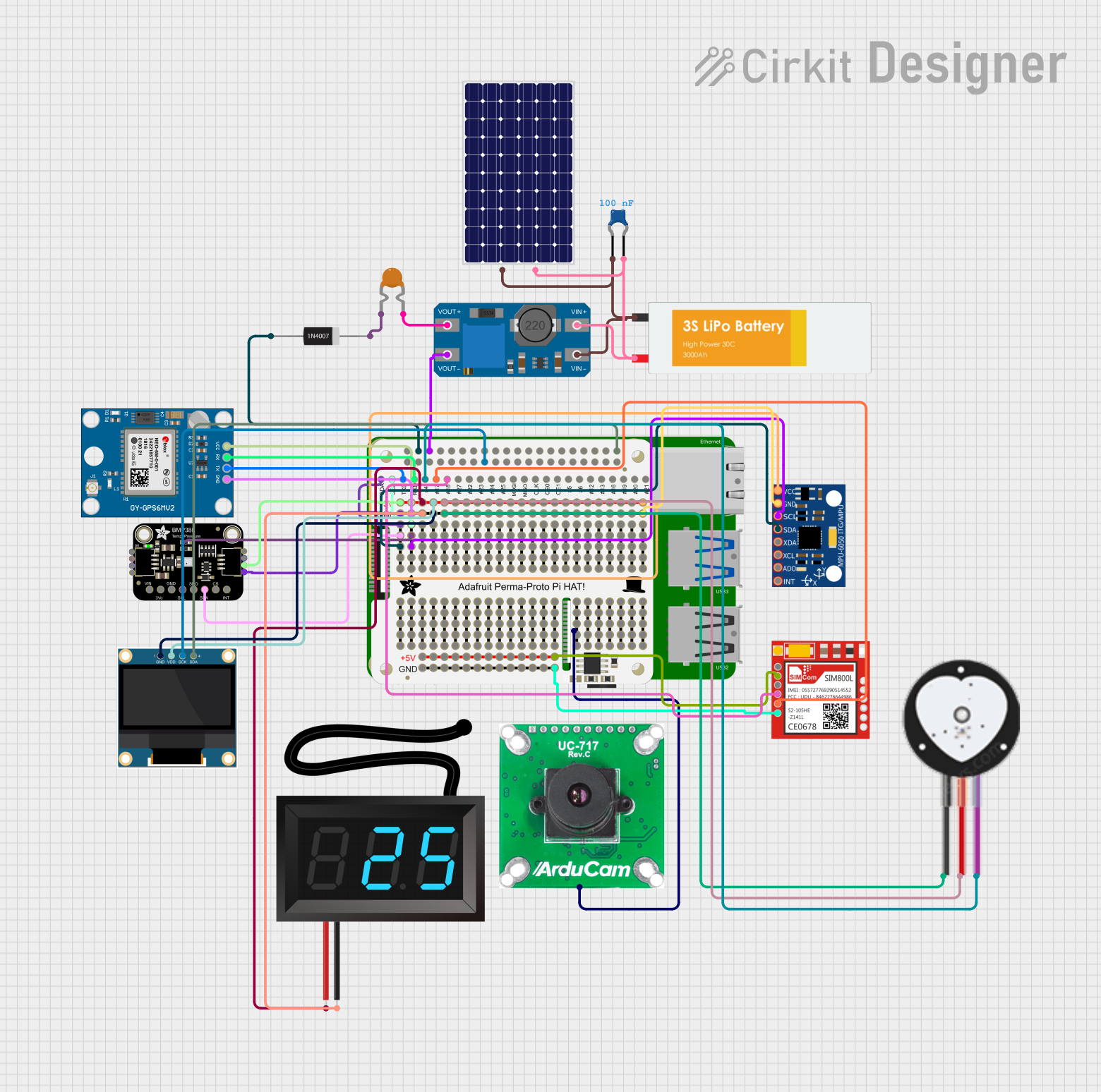


Explore Projects Built with Orange Pi
Common Applications and Use Cases
- Media Centers: Stream and play high-definition video and audio.
- IoT Projects: Serve as the core of smart home devices or industrial IoT systems.
- Robotics: Control robots with advanced processing and connectivity.
- Lightweight Servers: Host small-scale web servers, VPNs, or file-sharing systems.
- Educational Projects: Teach programming, electronics, and system design.
Technical Specifications
The Orange Pi Zero 3 is packed with features that make it a powerful and flexible SBC. Below are its key technical specifications:
Key Technical Details
- Processor: Allwinner H618 Quad-core Cortex-A53
- GPU: Mali-G31 MP2
- RAM: 1GB or 2GB DDR4 (depending on the model)
- Storage: MicroSD card slot (up to 128GB), eMMC (optional)
- Connectivity:
- Wi-Fi: 802.11 b/g/n/ac
- Bluetooth: 5.0
- Ethernet: 10/100/1000 Mbps
- Power Supply: 5V/2A via USB Type-C
- Operating Systems: Android, Debian, Ubuntu, and other Linux distributions
- GPIO Pins: 26-pin header for interfacing with external devices
- USB Ports: 1x USB 2.0, 1x USB Type-C (OTG)
- Video Output: HDMI 2.0 (4K@60fps)
- Dimensions: 48mm x 46mm
Pin Configuration and Descriptions
The Orange Pi Zero 3 features a 26-pin GPIO header for interfacing with external devices. Below is the pinout and description:
| Pin Number | Pin Name | Description |
|---|---|---|
| 1 | 3.3V | Power supply (3.3V) |
| 2 | 5V | Power supply (5V) |
| 3 | GPIO2 | General-purpose I/O, I2C SDA |
| 4 | 5V | Power supply (5V) |
| 5 | GPIO3 | General-purpose I/O, I2C SCL |
| 6 | GND | Ground |
| 7 | GPIO4 | General-purpose I/O |
| 8 | GPIO14 | UART TX |
| 9 | GND | Ground |
| 10 | GPIO15 | UART RX |
| 11 | GPIO17 | General-purpose I/O |
| 12 | GPIO18 | General-purpose I/O |
| 13 | GPIO27 | General-purpose I/O |
| 14 | GND | Ground |
| 15 | GPIO22 | General-purpose I/O |
| 16 | GPIO23 | General-purpose I/O |
| 17 | 3.3V | Power supply (3.3V) |
| 18 | GPIO24 | General-purpose I/O |
| 19 | GPIO10 | SPI MOSI |
| 20 | GND | Ground |
| 21 | GPIO9 | SPI MISO |
| 22 | GPIO25 | General-purpose I/O |
| 23 | GPIO11 | SPI CLK |
| 24 | GPIO8 | SPI CS0 |
| 25 | GND | Ground |
| 26 | GPIO7 | SPI CS1 |
Usage Instructions
How to Use the Orange Pi Zero 3 in a Circuit
- Powering the Board: Connect a 5V/2A power supply to the USB Type-C port.
- Operating System Installation:
- Download the desired OS image (e.g., Debian, Ubuntu) from the Orange Pi website.
- Flash the image onto a microSD card using tools like Balena Etcher.
- Insert the microSD card into the slot on the board.
- Connecting Peripherals:
- Use the HDMI port to connect a display.
- Attach a keyboard and mouse via the USB port.
- Connect to a network using Ethernet or Wi-Fi.
- GPIO Usage:
- Use the GPIO pins to interface with sensors, actuators, or other devices.
- Refer to the pinout table for proper connections.
Important Considerations and Best Practices
- Power Supply: Ensure a stable 5V/2A power source to avoid performance issues.
- Cooling: For intensive tasks, consider adding a heatsink or fan to prevent overheating.
- Static Protection: Handle the board with care to avoid static damage to components.
- Software Updates: Regularly update the OS and software packages for optimal performance and security.
Example: Blinking an LED with GPIO and Python
The following example demonstrates how to blink an LED connected to GPIO17 using Python.
Circuit Setup
- Connect the positive leg of the LED to GPIO17 (Pin 11).
- Connect the negative leg of the LED to a 330-ohm resistor, and then to GND (Pin 14).
Code
Import the required library
import RPi.GPIO as GPIO import time
Set up GPIO mode
GPIO.setmode(GPIO.BCM)
Define the GPIO pin for the LED
LED_PIN = 17
Set up the LED pin as an output
GPIO.setup(LED_PIN, GPIO.OUT)
try: while True: GPIO.output(LED_PIN, GPIO.HIGH) # Turn the LED on time.sleep(1) # Wait for 1 second GPIO.output(LED_PIN, GPIO.LOW) # Turn the LED off time.sleep(1) # Wait for 1 second except KeyboardInterrupt: # Clean up GPIO settings on exit GPIO.cleanup()
Troubleshooting and FAQs
Common Issues and Solutions
The board does not power on:
- Ensure the power supply provides 5V/2A.
- Check the USB Type-C cable for damage or poor connection.
No display output:
- Verify the HDMI cable and monitor are functioning.
- Ensure the correct OS image is flashed onto the microSD card.
Wi-Fi connectivity issues:
- Check the Wi-Fi credentials and signal strength.
- Update the OS to ensure the latest drivers are installed.
GPIO pins not working:
- Confirm the correct pin numbering (BCM vs. physical).
- Check for loose connections or incorrect wiring.
FAQs
Can I power the board via GPIO pins?
- Yes, you can supply 5V directly to the 5V pin, but ensure proper voltage regulation.
What is the maximum supported microSD card size?
- The Orange Pi Zero 3 supports microSD cards up to 128GB.
Does the board support 4K video output?
- Yes, it supports 4K@60fps via the HDMI 2.0 port.
Can I use the board for AI/ML applications?
- While it is not specifically designed for AI/ML, lightweight models can run on the board.
This concludes the documentation for the Orange Pi Zero 3. For further assistance, refer to the official Orange Pi website or community forums.