Cirkit Designer Logo
Cirkit Designer
Your all-in-one circuit design IDE
Home / 
Component Documentation

How to Use Voltage regulator 12v to 5v 3v: Examples, Pinouts, and Specs

Image of Voltage regulator 12v to 5v 3v
Cirkit Designer LogoDesign with Voltage regulator 12v to 5v 3v in Cirkit Designer

Introduction

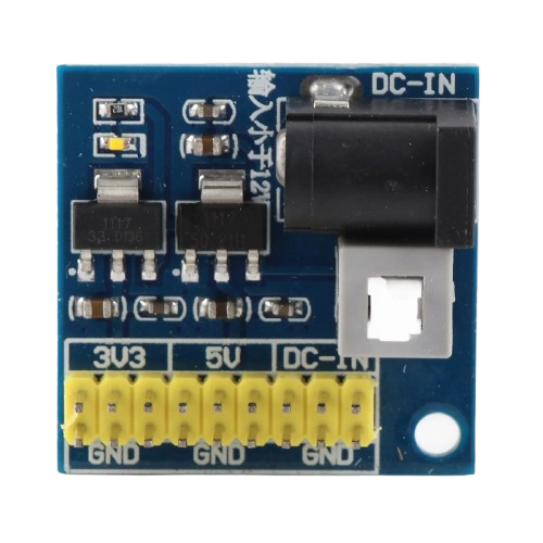
A voltage regulator is an indispensable component in electronic circuits, ensuring that devices receive a constant and appropriate voltage level for their operation. The 12V to 5V/3V voltage regulator is designed to take an input voltage of 12V and provide two regulated output voltages of 5V and 3V. This dual-output feature makes it highly versatile for powering various electronic devices that require different operating voltages.

Explore Projects Built with Voltage regulator 12v to 5v 3v

Use Cirkit Designer to design, explore, and prototype these projects online. Some projects support real-time simulation. Click "Open Project" to start designing instantly!
12V to 5V Power Supply with LED Indicator and Push Switch
Image of Power Supply LVCO: A project utilizing Voltage regulator 12v to 5v 3v in a practical application
This circuit is a 12V to 5V regulated power supply with an LED indicator. It uses a 5408 diode for reverse polarity protection, an LM340T5 7805 voltage regulator to step down the voltage to 5V, and a push switch to control the LED indicator. The circuit also includes capacitors for filtering and a resistor to limit the current through the LED.
Cirkit Designer LogoOpen Project in Cirkit Designer
Battery-Powered LED Control Circuit with Potentiometer and Transistors
Image of STROBE LIGHTS: A project utilizing Voltage regulator 12v to 5v 3v in a practical application
This circuit is a regulated power supply with a 12V battery input, a 7805 voltage regulator providing a 5V output, and a potentiometer for adjustable voltage control. It includes transistors and resistors for current regulation and an LED indicator to show the operational status.
Cirkit Designer LogoOpen Project in Cirkit Designer
Adjustable LED Driver with LM317 Voltage Regulator and Potentiometer
Image of Smart Light Intensity Adjustable Flashlight: A project utilizing Voltage regulator 12v to 5v 3v in a practical application
This circuit is a regulated power supply for a 12V, 10W LED, using an LM317 voltage regulator to control the output voltage. A potentiometer is used to adjust the voltage, and a 12V battery provides the input power.
Cirkit Designer LogoOpen Project in Cirkit Designer
Battery-Powered LED Indicator with 7805 Voltage Regulator
Image of 5V circuit: A project utilizing Voltage regulator 12v to 5v 3v in a practical application
This circuit uses a 9V battery to power a 7805 voltage regulator, which outputs a stable 5V. A toggle switch controls the input to the voltage regulator, and the regulated 5V output powers an LED through a 200-ohm resistor, allowing the LED to indicate when the circuit is active.
Cirkit Designer LogoOpen Project in Cirkit Designer

Explore Projects Built with Voltage regulator 12v to 5v 3v

Use Cirkit Designer to design, explore, and prototype these projects online. Some projects support real-time simulation. Click "Open Project" to start designing instantly!
Image of Power Supply LVCO: A project utilizing Voltage regulator 12v to 5v 3v in a practical application
12V to 5V Power Supply with LED Indicator and Push Switch
This circuit is a 12V to 5V regulated power supply with an LED indicator. It uses a 5408 diode for reverse polarity protection, an LM340T5 7805 voltage regulator to step down the voltage to 5V, and a push switch to control the LED indicator. The circuit also includes capacitors for filtering and a resistor to limit the current through the LED.
Cirkit Designer LogoOpen Project in Cirkit Designer
Image of STROBE LIGHTS: A project utilizing Voltage regulator 12v to 5v 3v in a practical application
Battery-Powered LED Control Circuit with Potentiometer and Transistors
This circuit is a regulated power supply with a 12V battery input, a 7805 voltage regulator providing a 5V output, and a potentiometer for adjustable voltage control. It includes transistors and resistors for current regulation and an LED indicator to show the operational status.
Cirkit Designer LogoOpen Project in Cirkit Designer
Image of Smart Light Intensity Adjustable Flashlight: A project utilizing Voltage regulator 12v to 5v 3v in a practical application
Adjustable LED Driver with LM317 Voltage Regulator and Potentiometer
This circuit is a regulated power supply for a 12V, 10W LED, using an LM317 voltage regulator to control the output voltage. A potentiometer is used to adjust the voltage, and a 12V battery provides the input power.
Cirkit Designer LogoOpen Project in Cirkit Designer
Image of 5V circuit: A project utilizing Voltage regulator 12v to 5v 3v in a practical application
Battery-Powered LED Indicator with 7805 Voltage Regulator
This circuit uses a 9V battery to power a 7805 voltage regulator, which outputs a stable 5V. A toggle switch controls the input to the voltage regulator, and the regulated 5V output powers an LED through a 200-ohm resistor, allowing the LED to indicate when the circuit is active.
Cirkit Designer LogoOpen Project in Cirkit Designer

Common Applications and Use Cases

  • Power supply for microcontrollers and digital circuits (5V)
  • Power supply for sensors and analog circuits (3V)
  • Battery-powered devices requiring stable voltage levels
  • Automotive electronics where the battery voltage (12V) needs to be stepped down
  • Portable electronics and mobile gadgets

Technical Specifications

Key Technical Details

  • Input Voltage (Vin): 12V DC
  • Output Voltage 1 (Vout1): 5V DC
  • Output Voltage 2 (Vout2): 3V DC
  • Maximum Output Current (Iout): Depends on the specific model (e.g., 1A for 5V, 500mA for 3V)
  • Voltage Regulation Accuracy: ±2%
  • Operating Temperature Range: -40°C to +85°C

Pin Configuration and Descriptions

Pin Number Pin Name Description
1 Vin Input voltage (12V)
2 GND Ground
3 Vout1 Regulated output voltage 1 (5V)
4 Vout2 Regulated output voltage 2 (3V)

Usage Instructions

How to Use the Component in a Circuit

  1. Connecting Input Voltage:

    • Connect the 12V input source to the Vin pin.
    • Ensure the ground of the input source is connected to the GND pin of the regulator.
  2. Accessing Output Voltages:

    • The 5V output can be accessed from the Vout1 pin.
    • The 3V output can be accessed from the Vout2 pin.
  3. Load Considerations:

    • Do not exceed the maximum output current rating for each output.
    • If the regulator is powering a high-current device, ensure adequate heat dissipation.

Important Considerations and Best Practices

  • Always check the polarity of connections to prevent damage to the regulator and connected devices.
  • Use decoupling capacitors close to the power pins of sensitive devices to smooth out voltage fluctuations.
  • If the regulator is used in an environment with large temperature variations, consider the effects of thermal derating.
  • For high-current applications, a heatsink may be necessary to prevent overheating.

Troubleshooting and FAQs

Common Issues

  • Voltage Drop Under Load: If the output voltage drops significantly under load, it may indicate that the load is drawing more current than the regulator can supply.
  • Overheating: If the regulator gets too hot, it may be due to excessive current draw or insufficient heat dissipation.

Solutions and Tips for Troubleshooting

  • Verify that the load does not exceed the maximum current rating.
  • Ensure proper heat dissipation through the use of a heatsink or by improving airflow around the regulator.
  • Check for any shorts or improper connections in the circuit that may cause excessive current draw.

FAQs

Q: Can I use this regulator to power a device that requires less than 3V? A: Yes, but you will need an additional step-down converter or a voltage divider to lower the voltage further.

Q: Is it possible to adjust the output voltages? A: This regulator provides fixed output voltages. For adjustable output voltages, a different type of regulator is required.

Q: Can I connect loads to both output voltages simultaneously? A: Yes, as long as the combined current draw does not exceed the regulator's maximum output current specifications.

Example Connection with Arduino UNO

// No specific code is required for using the voltage regulator with an Arduino UNO.
// However, you can connect the 5V output of the regulator to the 5V pin on the Arduino
// and the GND to the GND pin to power the board when not using USB power.

void setup() {
  // Initialize digital pin LED_BUILTIN as an output.
  pinMode(LED_BUILTIN, OUTPUT);
}

void loop() {
  // Turn the LED on (HIGH is the voltage level)
  digitalWrite(LED_BUILTIN, HIGH);
  // Wait for a second
  delay(1000);
  // Turn the LED off by making the voltage LOW
  digitalWrite(LED_BUILTIN, LOW);
   // Wait for a second
  delay(1000);
}

Note: When using the voltage regulator to power an Arduino UNO, ensure that the input voltage to the regulator does not exceed the recommended operating voltage for the Arduino (6-12V for the VIN pin, or up to 5V if bypassing the onboard regulator and supplying directly to the 5V pin).