Cirkit Designer Logo
Cirkit Designer
Your all-in-one circuit design IDE
Home / 
Component Documentation

How to Use Adafruit VL6180X Time of Flight Distance Sensor: Examples, Pinouts, and Specs

Image of Adafruit VL6180X Time of Flight Distance Sensor
Cirkit Designer LogoDesign with Adafruit VL6180X Time of Flight Distance Sensor in Cirkit Designer

Introduction

The Adafruit VL6180X Time of Flight Distance Sensor is a state-of-the-art sensor that utilizes time-of-flight (ToF) measurements of infrared light to determine the distance between the sensor and a target object. This technology allows for precise and accurate distance measurements, making it an ideal choice for a wide range of applications such as robotics, user interface controls, and obstacle detection systems.

Explore Projects Built with Adafruit VL6180X Time of Flight Distance Sensor

Use Cirkit Designer to design, explore, and prototype these projects online. Some projects support real-time simulation. Click "Open Project" to start designing instantly!
ESP8266 NodeMCU-Based Smart Eye Pressure Monitor with OLED Display and Wi-Fi Connectivity
Image of Copy of test 2 (7): A project utilizing Adafruit VL6180X Time of Flight Distance Sensor in a practical application
This circuit features an ESP8266 NodeMCU microcontroller interfaced with a VL53L0X time-of-flight distance sensor, a 0.96" OLED display, a piezo sensor, and a photodiode for light detection. The ESP8266 collects data from the sensors, displays readings on the OLED, and hosts a web server to present the information. It is likely designed for distance measurement, light intensity detection, and pressure sensing, with the capability to monitor and display these parameters in real-time over WiFi.
Cirkit Designer LogoOpen Project in Cirkit Designer
A-Star 32U4 Mini Controlled Servo with VL53L8CX Time-of-Flight Distance Sensing
Image of Servo con distance sensor: A project utilizing Adafruit VL6180X Time of Flight Distance Sensor in a practical application
This circuit features an A-Star 32U4 Mini microcontroller connected to a VL53L8CX Time-of-Flight distance sensor and a servo motor. The microcontroller powers both the sensor and the servo, and it is configured to communicate with the sensor via I2C (using pins 2 and 3 for SDA and SCL, respectively) and to control the servo via a PWM signal on pin 10. The purpose of the circuit is likely to measure distances and respond with movements of the servo based on the sensor readings.
Cirkit Designer LogoOpen Project in Cirkit Designer
Adafruit MPU6050 and VL6180X Sensor Interface with Servo Control
Image of wire: A project utilizing Adafruit VL6180X Time of Flight Distance Sensor in a practical application
This circuit features an Adafruit QT Py microcontroller interfaced with an Adafruit MPU6050 6-axis accelerometer/gyroscope and an Adafruit VL6180X Time of Flight (ToF) distance sensor, both connected via I2C communication. The QT Py also controls a Servomotor SG90, likely for physical actuation based on sensor inputs. The embedded code initializes the sensors, reads their data, and outputs the readings to a serial monitor, with the potential for motion control based on the sensor feedback.
Cirkit Designer LogoOpen Project in Cirkit Designer
ESP32-Based Battery-Powered RFID Reader with OLED Display and Distance Sensor
Image of Depthtron Project: A project utilizing Adafruit VL6180X Time of Flight Distance Sensor in a practical application
This circuit features an ESP32 microcontroller interfaced with a UHF RFID module, an Adafruit VL6180X Time of Flight Distance Sensor, an OLED display, and a pushbutton. The ESP32 reads distance data from the VL6180X sensor and displays it on the OLED, while also monitoring the state of the pushbutton and communicating with the RFID module via UART.
Cirkit Designer LogoOpen Project in Cirkit Designer

Explore Projects Built with Adafruit VL6180X Time of Flight Distance Sensor

Use Cirkit Designer to design, explore, and prototype these projects online. Some projects support real-time simulation. Click "Open Project" to start designing instantly!
Image of Copy of test 2 (7): A project utilizing Adafruit VL6180X Time of Flight Distance Sensor in a practical application
ESP8266 NodeMCU-Based Smart Eye Pressure Monitor with OLED Display and Wi-Fi Connectivity
This circuit features an ESP8266 NodeMCU microcontroller interfaced with a VL53L0X time-of-flight distance sensor, a 0.96" OLED display, a piezo sensor, and a photodiode for light detection. The ESP8266 collects data from the sensors, displays readings on the OLED, and hosts a web server to present the information. It is likely designed for distance measurement, light intensity detection, and pressure sensing, with the capability to monitor and display these parameters in real-time over WiFi.
Cirkit Designer LogoOpen Project in Cirkit Designer
Image of Servo con distance sensor: A project utilizing Adafruit VL6180X Time of Flight Distance Sensor in a practical application
A-Star 32U4 Mini Controlled Servo with VL53L8CX Time-of-Flight Distance Sensing
This circuit features an A-Star 32U4 Mini microcontroller connected to a VL53L8CX Time-of-Flight distance sensor and a servo motor. The microcontroller powers both the sensor and the servo, and it is configured to communicate with the sensor via I2C (using pins 2 and 3 for SDA and SCL, respectively) and to control the servo via a PWM signal on pin 10. The purpose of the circuit is likely to measure distances and respond with movements of the servo based on the sensor readings.
Cirkit Designer LogoOpen Project in Cirkit Designer
Image of wire: A project utilizing Adafruit VL6180X Time of Flight Distance Sensor in a practical application
Adafruit MPU6050 and VL6180X Sensor Interface with Servo Control
This circuit features an Adafruit QT Py microcontroller interfaced with an Adafruit MPU6050 6-axis accelerometer/gyroscope and an Adafruit VL6180X Time of Flight (ToF) distance sensor, both connected via I2C communication. The QT Py also controls a Servomotor SG90, likely for physical actuation based on sensor inputs. The embedded code initializes the sensors, reads their data, and outputs the readings to a serial monitor, with the potential for motion control based on the sensor feedback.
Cirkit Designer LogoOpen Project in Cirkit Designer
Image of Depthtron Project: A project utilizing Adafruit VL6180X Time of Flight Distance Sensor in a practical application
ESP32-Based Battery-Powered RFID Reader with OLED Display and Distance Sensor
This circuit features an ESP32 microcontroller interfaced with a UHF RFID module, an Adafruit VL6180X Time of Flight Distance Sensor, an OLED display, and a pushbutton. The ESP32 reads distance data from the VL6180X sensor and displays it on the OLED, while also monitoring the state of the pushbutton and communicating with the RFID module via UART.
Cirkit Designer LogoOpen Project in Cirkit Designer

Common Applications and Use Cases

  • Robotics: obstacle avoidance, navigation
  • User interfaces: gesture recognition, touchless control
  • Object detection: proximity sensing, level control
  • Drones: altitude sensing, collision avoidance

Technical Specifications

Key Technical Details

  • Operating Voltage: 2.6V to 3.5V
  • Current Consumption: 10mA (typical)
  • Range: Up to 200mm (actual range depends on object reflectivity and other environmental conditions)
  • Resolution: 1mm
  • Interface: I2C
  • Wavelength: 850nm (infrared light)

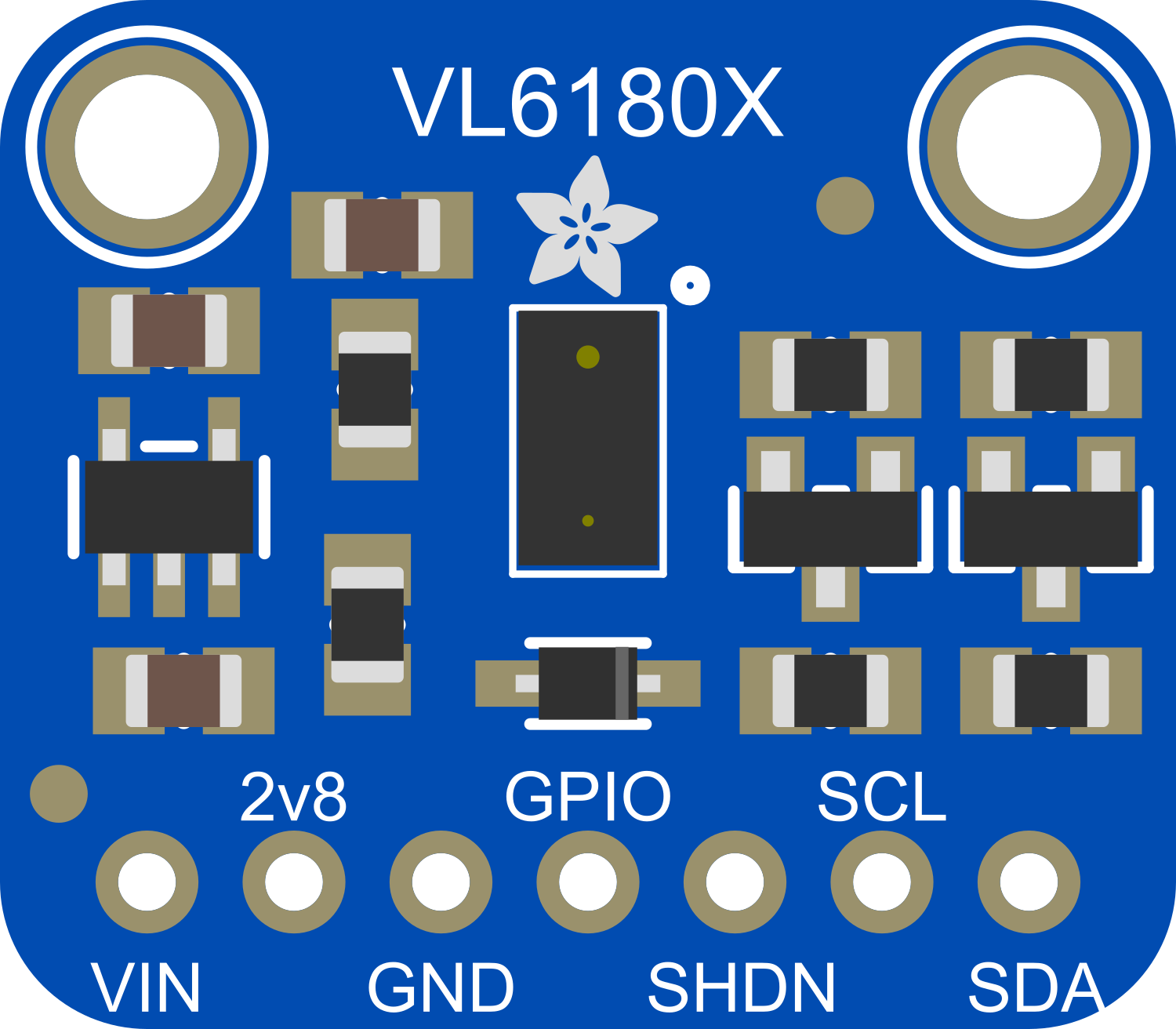
Pin Configuration and Descriptions

Pin Number Name Description
1 VIN Power supply (2.6V to 3.5V)
2 GND Ground connection
3 SCL I2C clock line
4 SDA I2C data line
5 GPIO1 General purpose I/O (optional use)
6 GPIO0 General purpose I/O (optional use)

Usage Instructions

How to Use the Component in a Circuit

  1. Connect the VIN pin to a 2.6V to 3.5V power supply.
  2. Connect the GND pin to the ground of the power supply.
  3. Connect the SCL and SDA pins to the I2C clock and data lines, respectively.
  4. If necessary, configure the GPIO pins for additional functionality.

Important Considerations and Best Practices

  • Ensure that the power supply voltage does not exceed the maximum rating of 3.5V.
  • Use pull-up resistors on the I2C lines if they are not already present on the microcontroller board.
  • Avoid placing objects with reflective surfaces too close to the sensor, as this may affect accuracy.
  • Keep the sensor away from direct sunlight and other strong infrared sources to prevent interference.

Example Code for Arduino UNO

#include <Wire.h>
#include <Adafruit_VL6180X.h>

Adafruit_VL6180X vl = Adafruit_VL6180X();

void setup() {
  Serial.begin(9600);
  // Wait for serial port to connect (necessary for Leonardo only)
  while (!Serial) {
    delay(1);
  }
  
  Serial.println("Adafruit VL6180X test");
  if (!vl.begin()) {
    Serial.println("Failed to find sensor");
    while (1);
  }
  Serial.println("Sensor found!");
}

void loop() {
  float lux = vl.readLux(VL6180X_ALS_GAIN_5);
  Serial.print("Lux: "); Serial.println(lux);
  
  uint8_t range = vl.readRange();
  uint8_t status = vl.readRangeStatus();
  
  if (status == VL6180X_ERROR_NONE) {
    Serial.print("Range: "); Serial.println(range);
  }

  // Some error occurred, print it out!
  
  if  ((status >= VL6180X_ERROR_SYSERR_1) && (status <= VL6180X_ERROR_SYSERR_5)) {
    Serial.println("System error");
  }
  else if (status == VL6180X_ERROR_ECEFAIL) {
    Serial.println("ECE failure");
  }
  else if (status == VL6180X_ERROR_NOCONVERGE) {
    Serial.println("No convergence");
  }
  else if (status == VL6180X_ERROR_RANGEIGNORE) {
    Serial.println("Ignoring range");
  }
  else if (status == VL6180X_ERROR_SNR) {
    Serial.println("Signal/Noise error");
  }
  else if (status == VL6180X_ERROR_RAWUFLOW) {
    Serial.println("Raw reading underflow");
  }
  else if (status == VL6180X_ERROR_RAWOFLOW) {
    Serial.println("Raw reading overflow");
  }
  else if (status == VL6180X_ERROR_RANGEUFLOW) {
    Serial.println("Range underflow");
  }
  else if (status == VL6180X_ERROR_RANGEOFLOW) {
    Serial.println("Range overflow");
  }
  
  delay(50);
}

Troubleshooting and FAQs

Common Issues Users Might Face

  • Inaccurate Readings: Ensure there are no reflective surfaces too close to the sensor and that the sensor is not exposed to direct sunlight or strong infrared sources.
  • No Response from Sensor: Check the wiring, especially the I2C connections, and ensure that the correct voltage is supplied.
  • Intermittent Functionality: Ensure that the I2C pull-up resistors are correctly sized and that there is no power supply instability.

Solutions and Tips for Troubleshooting

  • Double-check the wiring against the pin configuration table.
  • Use a logic analyzer or oscilloscope to check the I2C communication.
  • Make sure the sensor is not mounted near heat sources or in direct sunlight.
  • Consult the sensor's datasheet for more detailed troubleshooting steps.

FAQs

Q: What is the maximum range of the sensor? A: The maximum range is up to 200mm, but this can vary based on object reflectivity and environmental conditions.

Q: Can the sensor be used outdoors? A: The sensor can be used outdoors but should be shielded from direct sunlight and extreme weather conditions for accurate measurements.

Q: Is the sensor compatible with 5V systems? A: The sensor operates between 2.6V and 3.5V. A level shifter is required for use with 5V systems.

Q: How can I extend the range of the sensor? A: The range cannot be extended beyond its maximum capability; however, ensuring a clear path and minimal interference can help achieve the best possible range within its limits.