Cirkit Designer
Your all-in-one circuit design IDE
Home /
Component Documentation
How to Use DS3231 RTC: Examples, Pinouts, and Specs
Introduction
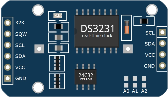
The DS3231 is a highly accurate, low-cost real-time clock (RTC) module with an integrated temperature-compensated crystal oscillator (TCXO) and crystal. It maintains seconds, minutes, hours, day, date, month, and year information, with automatic adjustment for leap years and months with fewer than 31 days. The module communicates with a microcontroller via I2C protocol.
Explore Projects Built with DS3231 RTC
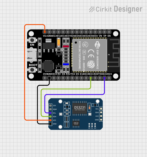
ESP32-Based Real-Time Clock Synchronization

This circuit connects an ESP32 Devkit V1 microcontroller with an RTC DS3231 real-time clock module. The ESP32 provides power to the RTC and communicates with it via I2C, with D21 and D22 serving as the data (SDA) and clock (SCL) lines, respectively. The common ground (GND) ensures a reference point for the voltages, and the 3V3 pin from the ESP32 powers the RTC module.
Dual RTC DS3231 Synchronization with Glyph C3 Microcontroller

This circuit integrates two RTC DS3231 real-time clock modules with a Glyph C3 microcontroller. The RTC modules are connected to the microcontroller via I2C communication protocol, using the SCL and SDA lines for clock and data respectively. Both RTC modules and the microcontroller share a common power supply (3V3) and ground (GND), indicating that they operate at the same voltage level.
ESP32-Based Real-Time Clock Synchronization
This circuit connects an ESP32 microcontroller to a DS3231 Real Time Clock (RTC) module. The ESP32's Vin and GND pins are connected to the VCC and GND pins of the DS3231, providing power to the RTC. The SCL and SDA pins of the DS3231 are connected to the D22 and D21 pins of the ESP32, respectively, enabling I2C communication between the microcontroller and the RTC module.
Arduino UNO with RTC DS3231 Timekeeping
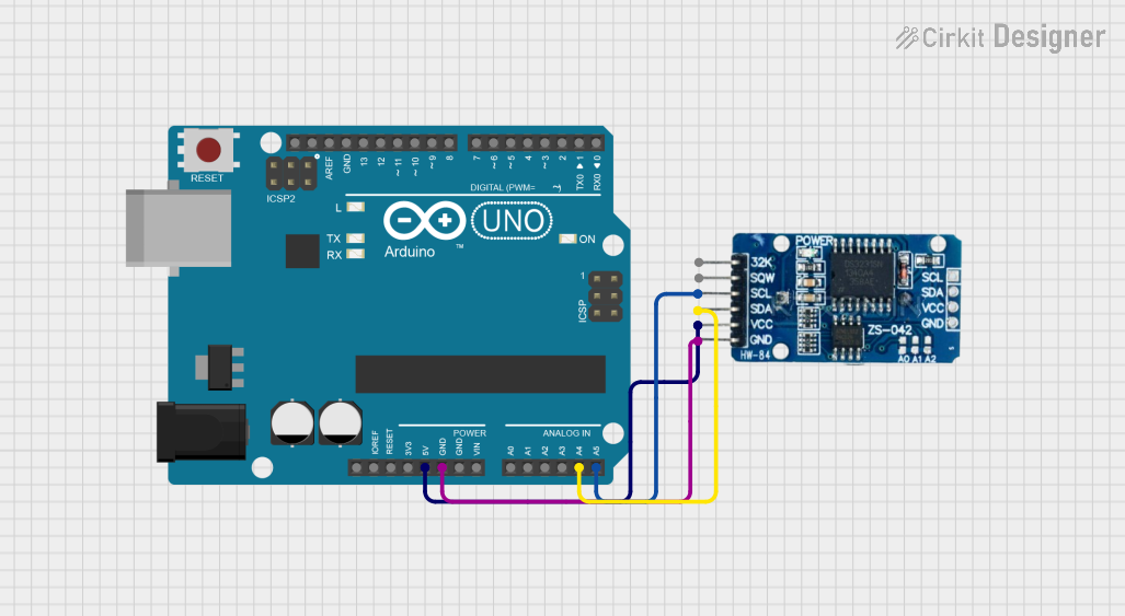
This circuit connects an Arduino UNO microcontroller with a DS3231 Real Time Clock (RTC) module. The Arduino provides 5V power and ground to the RTC and communicates with it via the I2C protocol using the A4 (SDA) and A5 (SCL) pins. The embedded code on the Arduino is used to initialize the RTC, check for power loss, set the current time if needed, and periodically read and print the current time to the serial monitor.
Explore Projects Built with DS3231 RTC
ESP32-Based Real-Time Clock Synchronization
This circuit connects an ESP32 Devkit V1 microcontroller with an RTC DS3231 real-time clock module. The ESP32 provides power to the RTC and communicates with it via I2C, with D21 and D22 serving as the data (SDA) and clock (SCL) lines, respectively. The common ground (GND) ensures a reference point for the voltages, and the 3V3 pin from the ESP32 powers the RTC module.
Dual RTC DS3231 Synchronization with Glyph C3 Microcontroller
This circuit integrates two RTC DS3231 real-time clock modules with a Glyph C3 microcontroller. The RTC modules are connected to the microcontroller via I2C communication protocol, using the SCL and SDA lines for clock and data respectively. Both RTC modules and the microcontroller share a common power supply (3V3) and ground (GND), indicating that they operate at the same voltage level.
ESP32-Based Real-Time Clock Synchronization
This circuit connects an ESP32 microcontroller to a DS3231 Real Time Clock (RTC) module. The ESP32's Vin and GND pins are connected to the VCC and GND pins of the DS3231, providing power to the RTC. The SCL and SDA pins of the DS3231 are connected to the D22 and D21 pins of the ESP32, respectively, enabling I2C communication between the microcontroller and the RTC module.
Arduino UNO with RTC DS3231 Timekeeping
This circuit connects an Arduino UNO microcontroller with a DS3231 Real Time Clock (RTC) module. The Arduino provides 5V power and ground to the RTC and communicates with it via the I2C protocol using the A4 (SDA) and A5 (SCL) pins. The embedded code on the Arduino is used to initialize the RTC, check for power loss, set the current time if needed, and periodically read and print the current time to the serial monitor.
Common Applications and Use Cases
- Timekeeping in embedded systems
- Data logging with time stamps
- Clocks and watches
- Alarm systems
- IoT devices requiring accurate timekeeping
Technical Specifications
Key Technical Details
- Time Accuracy: ±2ppm from 0°C to +40°C
- Battery Backup: Maintains timekeeping when main power is off
- Voltage: 2.3V to 5.5V
- Current: 200μA at 3.3V (active), 1μA (timekeeping)
- Operating Temperature: -40°C to +85°C
- Memory: 236 bytes of battery-backed SRAM
Pin Configuration and Descriptions
| Pin Number | Name | Description |
|---|---|---|
| 1 | VCC | Power supply (2.3V to 5.5V) |
| 2 | GND | Ground connection |
| 3 | SDA | Serial Data Line for I2C communication |
| 4 | SCL | Serial Clock Line for I2C communication |
| 5 | SQW | Square Wave/Interrupt Output |
| 6 | 32K | 32kHz Output |
| 7 | RST | Reset Input (Active Low) |
Usage Instructions
How to Use the DS3231 in a Circuit
- Connect VCC to a 2.3V to 5.5V power supply.
- Connect GND to the ground of the power supply.
- Connect SDA and SCL to the I2C data and clock lines of the microcontroller.
- Optionally, connect SQW to an interrupt pin on the microcontroller if square wave or alarm interrupt functionality is needed.
- Optionally, connect 32K to an input pin if a 32kHz clock signal is required.
- If a reset feature is needed, connect RST to a digital output pin; otherwise, it can be left unconnected or pulled high.
Important Considerations and Best Practices
- Ensure pull-up resistors are connected to the SDA and SCL lines, as they are required for proper I2C communication.
- If the module will be used in a battery-backed configuration, ensure a suitable coin cell battery is installed.
- Avoid exposing the module to extreme temperatures to maintain time accuracy.
Example Code for Arduino UNO
#include <Wire.h>
#include <RTClib.h>

RTC_DS3231 rtc;

void setup() {
  Serial.begin(9600);

  // Check if the RTC is connected correctly
  if (!rtc.begin()) {
    Serial.println("Couldn't find RTC");
    while (1);
  }

  // Check if the RTC lost power and if so, set the time
  if (rtc.lostPower()) {
    Serial.println("RTC lost power, let's set the time!");
    // The following line sets the RTC to the date & time this sketch was compiled
    rtc.adjust(DateTime(F(__DATE__), F(__TIME__)));
  }
}

void loop() {
  DateTime now = rtc.now();

  // Print the current date and time
  Serial.print(now.year(), DEC);
  Serial.print('/');
  Serial.print(now.month(), DEC);
  Serial.print('/');
  Serial.print(now.day(), DEC);
  Serial.print(" ");
  Serial.print(now.hour(), DEC);
  Serial.print(':');
  Serial.print(now.minute(), DEC);
  Serial.print(':');
  Serial.print(now.second(), DEC);
  Serial.println();

  delay(1000);
}
Troubleshooting and FAQs
Common Issues Users Might Face
- Time not accurate: Ensure the battery is installed correctly and has charge.
- I2C communication failure: Check pull-up resistors on SDA and SCL lines.
- Module not recognized: Verify wiring, ensure correct voltage supply, and check for soldering issues.
Solutions and Tips for Troubleshooting
- If the time drifts significantly, replace the battery to maintain accurate timekeeping during power outages.
- Use the
Wirelibrary'ssetClock()function to adjust I2C clock speed if communication issues arise. - Ensure the Arduino library for the DS3231 is correctly installed and up to date.
FAQs
- Q: Can the DS3231 be used without an external battery?
- A: Yes, but timekeeping will reset if power is lost.
- Q: What is the purpose of the 32K pin?
- A: It outputs a 32kHz square wave that can be used to drive timers or as a clock reference.
- Q: How do I set an alarm?
- A: Use the RTC library's alarm functions to configure and enable alarms.