How to Use YF-S201 Water Flow Meter: Examples, Pinouts, and Specs

Introduction
The YF-S201 Water Flow Meter is an electronic sensor designed to measure the rate of water flow through a pipe. It operates by using a rotor that spins in response to water flow, with a hall-effect sensor that outputs electrical pulses corresponding to the flow rate. This component is commonly used in irrigation systems, water conservation systems, beverage dispensing, and other applications where monitoring water consumption is essential.
Explore Projects Built with YF-S201 Water Flow Meter
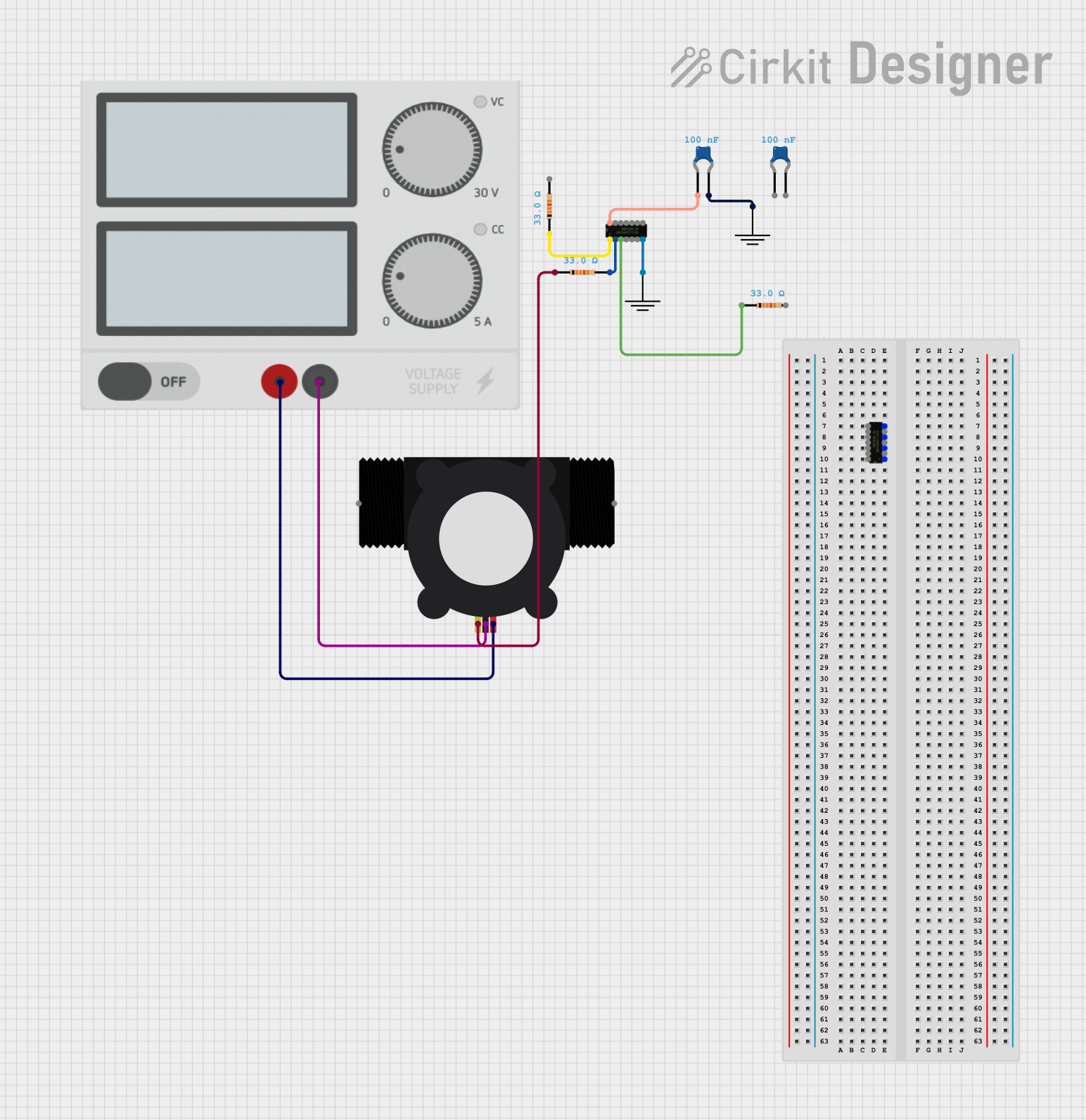
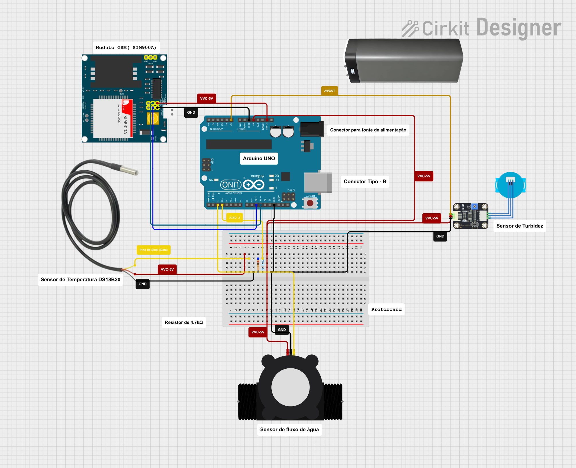
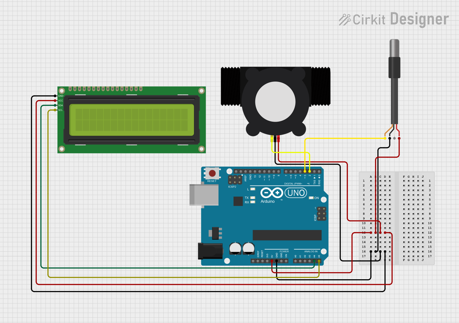
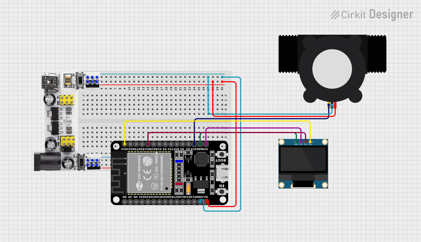
Explore Projects Built with YF-S201 Water Flow Meter
Technical Specifications
General Features
- Model: YF-S201
- Working Voltage: 5 to 18 V DC
- Max Current: 15 mA (at 5 V)
- Flow Rate Range: 1 to 30 liters per minute
- Working Temperature: -25 to +80°C
- Accuracy: ±5%
- Output Pulse High Level: >4.5 V (input voltage 5 V)
- Output Pulse Low Level: <0.5 V (input voltage 5 V)
- Pulse Frequency: F = 7.5 * Q (Q in L/min)
Pin Configuration and Descriptions
| Pin Number | Description | Notes |
|---|---|---|
| 1 | GND (Ground) | Connect to system ground |
| 2 | VCC (Power Supply) | 5 to 18 V DC |
| 3 | Signal Output | Outputs pulse signal |
Usage Instructions
Integration with a Circuit
- Connect the VCC pin to a 5V power supply.
- Connect the GND pin to the ground of the power supply.
- Connect the Signal Output pin to a digital input pin on a microcontroller, such as an Arduino UNO.
Important Considerations and Best Practices
- Ensure the water flow direction matches the arrow on the sensor.
- Avoid subjecting the sensor to mechanical shocks and chemical corrosion.
- Install the sensor in a location where it is not subjected to significant vibrations.
- Use a pull-up resistor if the microcontroller input pin does not have an internal pull-up feature.
- Filter the sensor signal if there is a significant amount of "noise" in the system.
Example Code for Arduino UNO
// Define the pin connected to the flow meter
const int flowPin = 2;
// Count of pulses from the flow meter
volatile int flowPulseCount = 0;

// Interrupt Service Routine for flow meter
void flowISR() {
  flowPulseCount++;
}

void setup() {
  Serial.begin(9600);
  pinMode(flowPin, INPUT);
  // Attach interrupt to the ISR, triggered by a RISING pulse
  attachInterrupt(digitalPinToInterrupt(flowPin), flowISR, RISING);
}

void loop() {
  // Disable interrupt when calculating flow rate
  noInterrupts();
  int flowPulseCountCopy = flowPulseCount;
  flowPulseCount = 0;
  interrupts();

  // Calculate the flow rate in liters per minute
  // Pulse frequency (Hz) = 7.5 * Flow rate (L/min)
  float flowRate = flowPulseCountCopy / 7.5;
  Serial.print("Flow rate: ");
  Serial.print(flowRate);
  Serial.println(" L/min");

  // Wait for 1 second before reading again
  delay(1000);
}
Troubleshooting and FAQs
Common Issues
- No signal output: Ensure the power supply is correctly connected and within the specified voltage range.
- Inaccurate readings: Verify that there are no air bubbles in the pipe and that the sensor is fully submerged in the water flow.
- Erratic readings: Check for potential electrical noise and consider using a signal filter or shielded cables.
Solutions and Tips
- If the sensor does not output a signal, check the connections and the power supply.
- For inaccurate readings, recalibrate the sensor or check for obstructions in the rotor.
- In case of erratic readings, ensure the sensor is mounted securely and away from sources of vibration or magnetic interference.
FAQs
Q: Can the YF-S201 be used with hot water? A: The sensor can operate within a temperature range of -25 to +80°C. It is suitable for hot water applications within this range.
Q: How can I increase the accuracy of the sensor? A: Ensure proper installation, avoid air bubbles in the line, and use a consistent power supply. Calibration with a known volume of water can also improve accuracy.
Q: Is the YF-S201 sensor waterproof? A: The sensor is designed to measure water flow within a pipe and is typically water-resistant. However, the electronic components should not be submerged or exposed to moisture.