
How to Use Reed switch: Examples, Pinouts, and Specs

 Design with Reed switch in Cirkit Designer
Introduction
A Reed switch is an electromagnetic switch that opens and closes in response to a magnetic field. It consists of two ferromagnetic contacts sealed within a glass tube, which close when exposed to a magnetic field and open when the field is removed. Reed switches are widely used in applications requiring non-contact switching, such as proximity sensors, security systems, and automotive electronics. Their simplicity, reliability, and low power consumption make them ideal for a variety of use cases.
Explore Projects Built with Reed switch
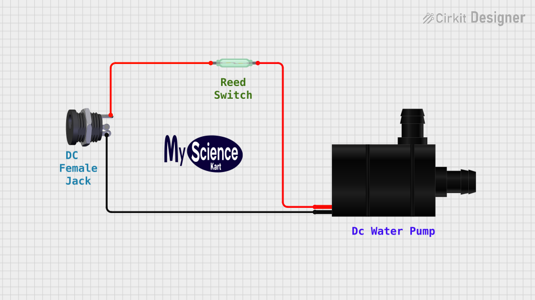 Open Project in Cirkit Designer
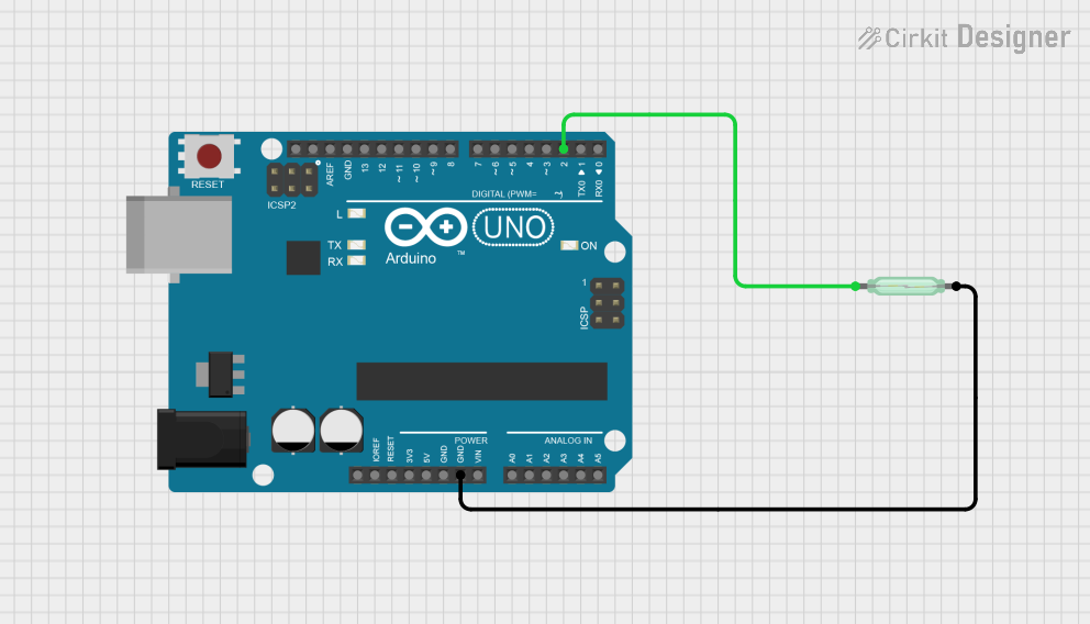 Open Project in Cirkit Designer
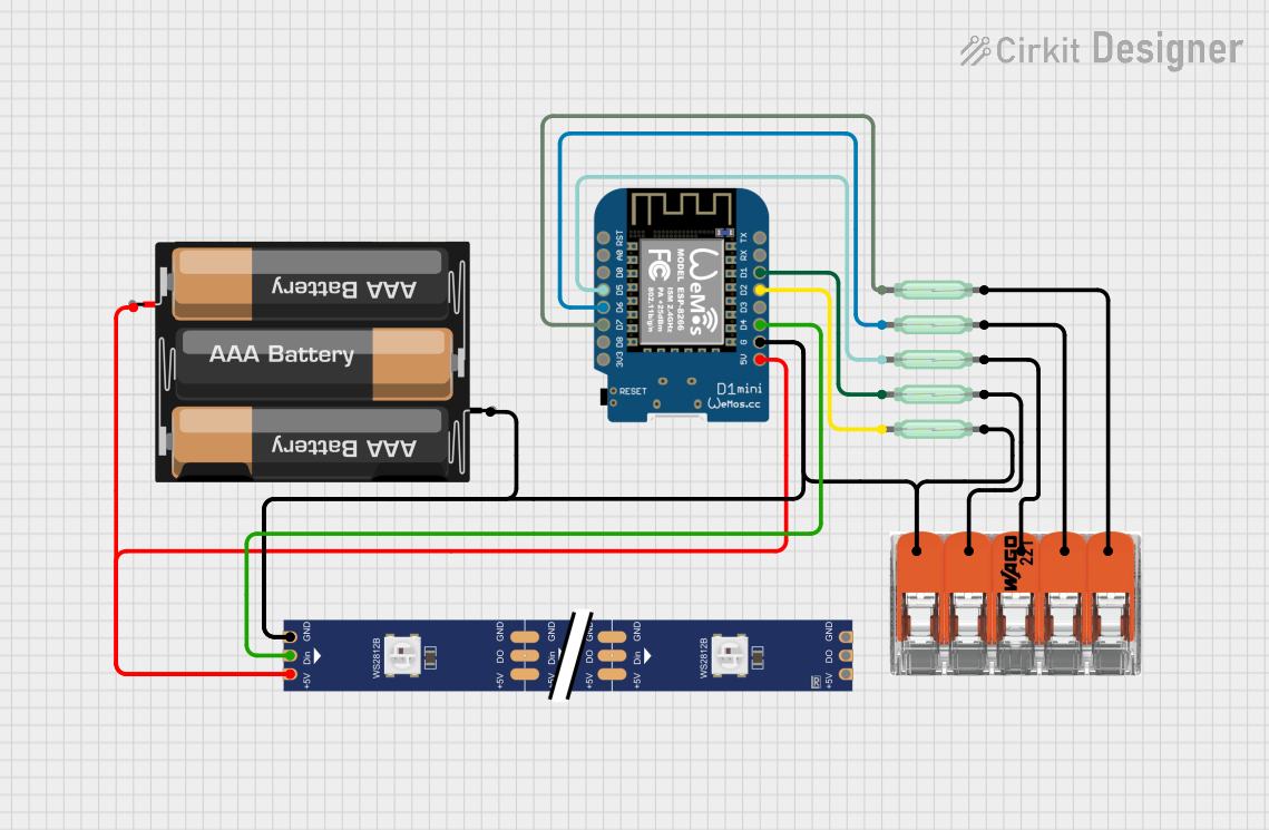 Open Project in Cirkit Designer
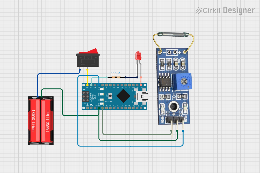 Open Project in Cirkit Designer
Explore Projects Built with Reed switch
Open Project in Cirkit DesignerOpen Project in Cirkit DesignerOpen Project in Cirkit DesignerOpen Project in Cirkit DesignerCommon Applications:
- Door and window sensors in security systems
- Proximity detection in industrial automation
- Position sensing in robotics
- Speed sensing in bicycles and vehicles
- Liquid level detection in tanks
Technical Specifications
Below are the key technical details of a typical Reed switch. Note that specifications may vary depending on the manufacturer and model.
General Specifications:
- Switching Voltage: Up to 200 V DC (varies by model)
- Switching Current: Typically 0.5 A (500 mA) max
- Contact Resistance: 50 mΩ to 200 mΩ (when closed)
- Insulation Resistance: >10⁹ Ω (when open)
- Response Time: 0.5 ms to 2 ms
- Operating Temperature: -40°C to +125°C
- Lifetime: Up to 10⁷ operations (depending on load)
Pin Configuration:
Reed switches typically have two leads (pins) that serve as the switch terminals. These leads are not polarized, meaning the switch can be connected in either orientation.
| Pin Number | Description |
|---|---|
| 1 | Switch Terminal 1 |
| 2 | Switch Terminal 2 |
Usage Instructions
How to Use a Reed Switch in a Circuit:
- Placement in Circuit: Connect the Reed switch in series with the load or as part of a sensing circuit. Since it is not polarized, either terminal can be connected to the positive or negative side of the circuit.
- Magnet Placement: Place a magnet near the Reed switch to close the contacts. The distance at which the switch activates depends on the magnet's strength and the switch's sensitivity.
- Pull-Up/Down Resistor: When using the Reed switch with a microcontroller, include a pull-up or pull-down resistor to ensure a stable signal when the switch is open.
Example Circuit with Arduino UNO:
Below is an example of how to use a Reed switch with an Arduino UNO to detect the presence of a magnetic field.
Circuit Connections:
- Connect one terminal of the Reed switch to a digital input pin (e.g., pin 2) on the Arduino.
- Connect the other terminal to the ground (GND).
- Add a 10 kΩ pull-up resistor between the digital input pin and the 5V supply.
Arduino Code:
// Reed Switch Example with Arduino UNO
// This code reads the state of a Reed switch and turns on an LED when the switch
// is closed (magnet present).

const int reedSwitchPin = 2; // Pin connected to the Reed switch
const int ledPin = 13;       // Pin connected to the onboard LED

void setup() {
  pinMode(reedSwitchPin, INPUT_PULLUP); // Set Reed switch pin as input with pull-up
  pinMode(ledPin, OUTPUT);             // Set LED pin as output
  Serial.begin(9600);                  // Initialize serial communication
}

void loop() {
  int reedState = digitalRead(reedSwitchPin); // Read the state of the Reed switch

  if (reedState == LOW) { // LOW means the switch is closed (magnet present)
    digitalWrite(ledPin, HIGH); // Turn on the LED
    Serial.println("Magnet detected!");
  } else {
    digitalWrite(ledPin, LOW); // Turn off the LED
    Serial.println("No magnet detected.");
  }

  delay(100); // Small delay for stability
}
Important Considerations:
- Debouncing: Reed switches may produce noise or "bounce" when switching states. Use software debouncing or a capacitor across the terminals to filter out noise.
- Current Limiting: Avoid exceeding the maximum current rating to prevent damage to the contacts.
- Magnet Strength: Ensure the magnet used is strong enough to reliably activate the switch at the desired distance.
Troubleshooting and FAQs
Common Issues:
- Switch Not Activating:
- Ensure the magnet is strong enough and positioned correctly.
- Check for loose or incorrect connections in the circuit.
- Unstable Readings:
- Add a pull-up or pull-down resistor to stabilize the signal.
- Use software or hardware debouncing to eliminate noise.
- Switch Stuck in One State:
- Verify that the switch is not damaged or stuck due to excessive current or mechanical stress.
FAQs:
Q: Can I use a Reed switch to detect non-magnetic objects?
A: No, Reed switches only respond to magnetic fields. For non-magnetic object detection, consider using other sensors like infrared or ultrasonic sensors.
Q: How far can the magnet be from the Reed switch?
A: The activation distance depends on the magnet's strength and the sensitivity of the Reed switch. Typical distances range from a few millimeters to several centimeters.
Q: Can a Reed switch handle AC signals?
A: Yes, Reed switches can handle both AC and DC signals, but ensure the voltage and current ratings are not exceeded.
Q: How do I protect the Reed switch from high currents?
A: Use a current-limiting resistor or a relay to handle higher currents indirectly.
By following these guidelines and best practices, you can effectively integrate a Reed switch into your projects for reliable and efficient operation.