Cirkit Designer Logo
Cirkit Designer
Your all-in-one circuit design IDE
Home / 
Component Documentation

How to Use CD4511: Examples, Pinouts, and Specs

Image of CD4511
Cirkit Designer LogoDesign with CD4511 in Cirkit Designer

Introduction

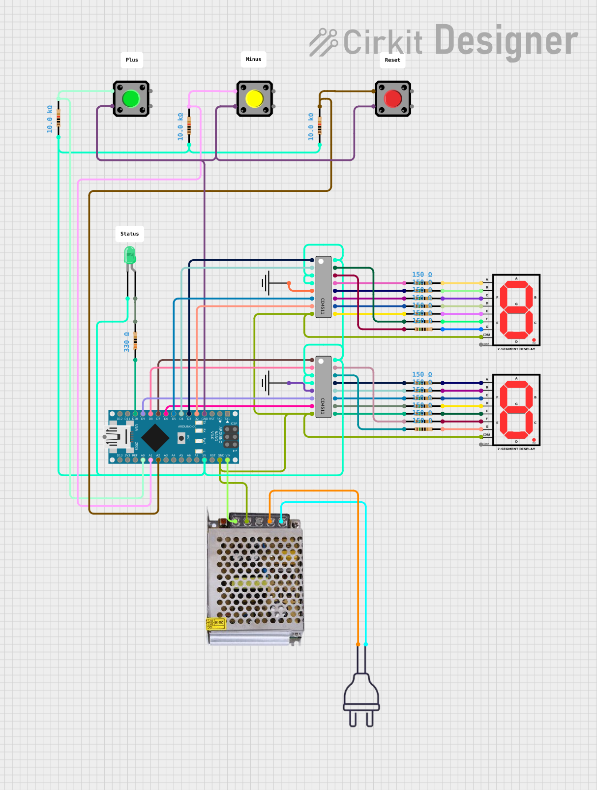
The CD4511 is a BCD-to-7 segment decoder/driver IC that is widely used in digital electronics to convert binary-coded decimal (BCD) inputs into the corresponding 7-segment display outputs. This component is essential in applications requiring numerical displays like digital clocks, calculators, and counters. By simplifying the process of driving 7-segment displays, the CD4511 allows for efficient and straightforward implementation in various electronic projects.

Explore Projects Built with CD4511

Use Cirkit Designer to design, explore, and prototype these projects online. Some projects support real-time simulation. Click "Open Project" to start designing instantly!
Arduino Nano Controlled 7-Segment Display Interface
Image of Praxisprojekt: A project utilizing CD4511 in a practical application
This circuit appears to be a digital display system using an Arduino Nano to drive two CD4511 BCD to 7-segment latch/decoder/drivers, which in turn control two 7-segment displays. The Arduino receives input from three pushbuttons, each with a pull-up resistor, and controls the segments of the displays through the CD4511 ICs. Additionally, there is a green LED that might serve as a power indicator or status light, connected through a current-limiting resistor.
Cirkit Designer LogoOpen Project in Cirkit Designer
Lilygo 7670e-Based Smart Interface with LCD Display and Keypad
Image of Paower: A project utilizing CD4511 in a practical application
This circuit features a Lilygo 7670e microcontroller interfaced with a 16x2 I2C LCD for display, a 4X4 membrane matrix keypad for input, and an arcade button for additional control. It also includes a 4G antenna and a GPS antenna for communication and location tracking capabilities.
Cirkit Designer LogoOpen Project in Cirkit Designer
Arduino 101 Based RFID and GSM Security System with I2C LCD Display and RTC
Image of id scanner with messaging system: A project utilizing CD4511 in a practical application
This circuit features an Arduino 101 microcontroller interfaced with an RFID-RC522 module for RFID reading, a GSM SIM900 module for cellular communication, a DS3231 Real Time Clock for timekeeping, and an I2C LCD screen for display. The Arduino controls a buzzer connected to its D7 pin and communicates with the GSM module via serial connection on pins D0/RX and D1/TX. The RFID, RTC, and LCD modules are powered by the Arduino's 5V and 3.3V outputs, and they use I2C (SCL/SDA) for communication, except for the RFID module which uses SPI (MISO/MOSI/SCK) and a digital pin for reset (D9).
Cirkit Designer LogoOpen Project in Cirkit Designer
Battery-Powered Emergency Alert System with NUCLEO-F072RB, SIM800L, and GPS NEO 6M
Image of women safety: A project utilizing CD4511 in a practical application
This circuit is an emergency alert system that uses a NUCLEO-F072RB microcontroller to send SMS alerts and make calls via a SIM800L GSM module, while obtaining location data from a GPS NEO 6M module. The system is powered by a Li-ion battery and includes a TP4056 module for battery charging and protection, with a rocker switch to control power to the microcontroller.
Cirkit Designer LogoOpen Project in Cirkit Designer

Explore Projects Built with CD4511

Use Cirkit Designer to design, explore, and prototype these projects online. Some projects support real-time simulation. Click "Open Project" to start designing instantly!
Image of Praxisprojekt: A project utilizing CD4511 in a practical application
Arduino Nano Controlled 7-Segment Display Interface
This circuit appears to be a digital display system using an Arduino Nano to drive two CD4511 BCD to 7-segment latch/decoder/drivers, which in turn control two 7-segment displays. The Arduino receives input from three pushbuttons, each with a pull-up resistor, and controls the segments of the displays through the CD4511 ICs. Additionally, there is a green LED that might serve as a power indicator or status light, connected through a current-limiting resistor.
Cirkit Designer LogoOpen Project in Cirkit Designer
Image of Paower: A project utilizing CD4511 in a practical application
Lilygo 7670e-Based Smart Interface with LCD Display and Keypad
This circuit features a Lilygo 7670e microcontroller interfaced with a 16x2 I2C LCD for display, a 4X4 membrane matrix keypad for input, and an arcade button for additional control. It also includes a 4G antenna and a GPS antenna for communication and location tracking capabilities.
Cirkit Designer LogoOpen Project in Cirkit Designer
Image of id scanner with messaging system: A project utilizing CD4511 in a practical application
Arduino 101 Based RFID and GSM Security System with I2C LCD Display and RTC
This circuit features an Arduino 101 microcontroller interfaced with an RFID-RC522 module for RFID reading, a GSM SIM900 module for cellular communication, a DS3231 Real Time Clock for timekeeping, and an I2C LCD screen for display. The Arduino controls a buzzer connected to its D7 pin and communicates with the GSM module via serial connection on pins D0/RX and D1/TX. The RFID, RTC, and LCD modules are powered by the Arduino's 5V and 3.3V outputs, and they use I2C (SCL/SDA) for communication, except for the RFID module which uses SPI (MISO/MOSI/SCK) and a digital pin for reset (D9).
Cirkit Designer LogoOpen Project in Cirkit Designer
Image of women safety: A project utilizing CD4511 in a practical application
Battery-Powered Emergency Alert System with NUCLEO-F072RB, SIM800L, and GPS NEO 6M
This circuit is an emergency alert system that uses a NUCLEO-F072RB microcontroller to send SMS alerts and make calls via a SIM800L GSM module, while obtaining location data from a GPS NEO 6M module. The system is powered by a Li-ion battery and includes a TP4056 module for battery charging and protection, with a rocker switch to control power to the microcontroller.
Cirkit Designer LogoOpen Project in Cirkit Designer

Technical Specifications

Key Technical Details

  • Supply Voltage (Vdd): 3V to 18V
  • Input Voltage (Vi): -0.5V to Vdd + 0.5V
  • Output Current (Io): 25mA (max)
  • Power Dissipation (Pd): 500mW
  • Operating Temperature Range: -55°C to +125°C

Pin Configuration and Descriptions

Pin Number Name Description
1 LE Latch Enable Input
2 B BCD Input B (MSB)
3 A BCD Input A (LSB)
4 GND Ground (0V)
5 C BCD Input C
6 D BCD Input D
7 BL Blanking Input (Active Low)
8 LT Lamp Test Input (Active Low)
9 e Segment 'e' Output
10 d Segment 'd' Output
11 c Segment 'c' Output
12 b Segment 'b' Output
13 a Segment 'a' Output
14 g Segment 'g' Output
15 f Segment 'f' Output
16 Vdd Positive Supply Voltage

Usage Instructions

How to Use the CD4511 in a Circuit

  1. Power Supply: Connect pin 16 (Vdd) to a positive supply voltage within the range of 3V to 18V and pin 4 (GND) to the ground of the circuit.
  2. Input Connections: Apply the BCD code to pins 3 (A), 2 (B), 5 (C), and 6 (D), with A being the least significant bit (LSB) and D the most significant bit (MSB).
  3. Output Connections: Connect the outputs (pins 9 to 15) to the corresponding segments of the 7-segment display.
  4. Control Pins: Optionally, use pin 1 (LE) to latch the input data, pin 7 (BL) to blank the display, and pin 8 (LT) for testing all segments.

Important Considerations and Best Practices

  • Ensure that the supply voltage does not exceed the maximum rating to prevent damage to the IC.
  • Use current-limiting resistors with the 7-segment display to protect the segments from excessive current.
  • When not using control pins (LE, BL, LT), connect them to the appropriate logic level (High or Low) as per the desired operation.

Troubleshooting and FAQs

Common Issues

  • Display Not Lighting Up: Check if the supply voltage is within the specified range and if all connections are secure.
  • Incorrect Display Output: Verify that the BCD inputs are correctly applied and that there are no short circuits on the output pins.
  • Dim Display: Ensure that the current-limiting resistors are of the correct value and that the supply voltage is adequate.

Solutions and Tips

  • Double-check the pin connections and the orientation of the IC in the circuit.
  • Use a multimeter to measure the voltage levels at the inputs and outputs to ensure they match the expected logic levels.
  • If using multiple CD4511 ICs, ensure that each IC has its own current-limiting resistors for the display segments.

FAQs

Q: Can the CD4511 drive multiple 7-segment displays? A: Yes, but each segment of each display will need its own current-limiting resistor, and additional circuitry may be required for multiplexing.

Q: What is the purpose of the latch enable (LE) pin? A: The LE pin allows the user to latch or hold the input BCD value. When LE is high, the output will follow the input. When LE is low, the output will hold the last input state.

Q: Is it necessary to use the lamp test and blanking functions? A: No, these functions are optional. If not used, the LT pin should be connected to Vdd, and the BL pin should be connected to Vdd to ensure normal operation.

Example Code for Arduino UNO

// Define the BCD input pins
int pinA = 2; // BCD input A (LSB)
int pinB = 3; // BCD input B
int pinC = 4; // BCD input C
int pinD = 5; // BCD input D (MSB)

void setup() {
  // Set the BCD pins as outputs
  pinMode(pinA, OUTPUT);
  pinMode(pinB, OUTPUT);
  pinMode(pinC, OUTPUT);
  pinMode(pinD, OUTPUT);
}

void loop() {
  // Loop through numbers 0 to 9 and display on 7-segment
  for (int number = 0; number < 10; number++) {
    displayNumber(number);
    delay(1000); // Wait for 1 second
  }
}

void displayNumber(int number) {
  // Convert the number to BCD and output to CD4511
  digitalWrite(pinA, number & 0x01);
  digitalWrite(pinB, number & 0x02);
  digitalWrite(pinC, number & 0x04);
  digitalWrite(pinD, number & 0x08);
}

This example demonstrates how to connect the CD4511 to an Arduino UNO and cycle through the numbers 0 to 9 on a 7-segment display. The BCD inputs are connected to digital pins 2 through 5, and the displayNumber function converts an integer to its BCD equivalent and outputs it to the CD4511.