Cirkit Designer Logo
Cirkit Designer
Your all-in-one circuit design IDE
Home / 
Component Documentation

How to Use Adafruit 12-Channel 16-bit PWM LED Driver - SPI: Examples, Pinouts, and Specs

Image of Adafruit 12-Channel 16-bit PWM LED Driver - SPI
Cirkit Designer LogoDesign with Adafruit 12-Channel 16-bit PWM LED Driver - SPI in Cirkit Designer

Introduction

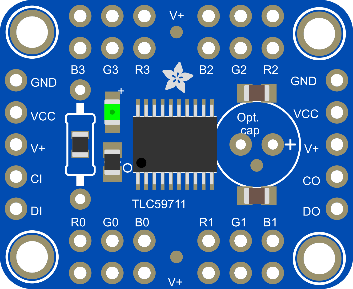
The Adafruit 12-Channel 16-bit PWM LED Driver is an electronic component designed for controlling multiple LEDs with high precision. Utilizing the Serial Peripheral Interface (SPI) for communication, this driver can manage up to 12 individual channels, making it ideal for complex lighting projects, including architectural lighting, digital signage, and custom LED installations. With its 16-bit PWM resolution, it offers fine-grained control over the brightness and color of each connected LED, enabling smooth transitions and a wide range of dimming options.

Explore Projects Built with Adafruit 12-Channel 16-bit PWM LED Driver - SPI

Use Cirkit Designer to design, explore, and prototype these projects online. Some projects support real-time simulation. Click "Open Project" to start designing instantly!
Arduino-Controlled Servo Driver for Multi-Channel PWM Applications
Image of SPG: A project utilizing Adafruit 12-Channel 16-bit PWM LED Driver - SPI in a practical application
This circuit is designed to control multiple servo motors using an Arduino Mega 2560 microcontroller and an Adafruit 16-Channel 12-bit PWM Servo Driver. The Arduino communicates with the PWM driver over I2C (using SDA and SCL lines) to send PWM signals to individual servos for precise angle control. A separate 5V power supply provides power to the PWM driver and the servos, ensuring stable operation for high-current applications.
Cirkit Designer LogoOpen Project in Cirkit Designer
Arduino-Controlled Multi-Servo Positioning System with Potentiometer Feedback
Image of robootic arm: A project utilizing Adafruit 12-Channel 16-bit PWM LED Driver - SPI in a practical application
This circuit uses an Arduino UNO to control five servos through an Adafruit 16-Channel 12-bit PWM Servo Driver, with the position of each servo being adjusted by a corresponding potentiometer. The Arduino reads the analog values from the potentiometers connected to its analog inputs and sends PWM signals to the servos via the I2C-connected PWM driver. The servos are powered by a separate power supply that also powers the PWM driver, ensuring adequate current for servo operation.
Cirkit Designer LogoOpen Project in Cirkit Designer
Arduino Nano Controlled Robotics System with Wireless Communication and Touch Sensing
Image of AI: A project utilizing Adafruit 12-Channel 16-bit PWM LED Driver - SPI in a practical application
This circuit features two Arduino Nanos controlling a variety of components. One Arduino interfaces with a 12-bit PWM servo driver to manage multiple servos, an OLED display, a stepper motor via an A4988 driver, and communicates using an NRF24L01 wireless module. The other Arduino handles inputs from several TTP233 touch sensors and also communicates wirelessly using its own NRF24L01 module. Power management is handled by a 12V battery, a step-down converter to 5V, and rocker switches to control power flow.
Cirkit Designer LogoOpen Project in Cirkit Designer
Raspberry Pi 5 Controlled Traffic Light System with PWM Servo Driver
Image of traffic : A project utilizing Adafruit 12-Channel 16-bit PWM LED Driver - SPI in a practical application
This circuit features a Raspberry Pi 5 microcontroller connected to an Adafruit 16-Channel 12-bit PWM Servo Driver via I2C communication protocol, which in turn controls multiple traffic lights and individual green LEDs. The Raspberry Pi provides power and ground connections to the PWM driver, and the driver outputs PWM signals to control the red, yellow, and green lights of each traffic light, as well as additional green LEDs. The purpose of this circuit is likely to simulate a traffic light control system, with the capability to individually manage each light's state.
Cirkit Designer LogoOpen Project in Cirkit Designer

Explore Projects Built with Adafruit 12-Channel 16-bit PWM LED Driver - SPI

Use Cirkit Designer to design, explore, and prototype these projects online. Some projects support real-time simulation. Click "Open Project" to start designing instantly!
Image of SPG: A project utilizing Adafruit 12-Channel 16-bit PWM LED Driver - SPI in a practical application
Arduino-Controlled Servo Driver for Multi-Channel PWM Applications
This circuit is designed to control multiple servo motors using an Arduino Mega 2560 microcontroller and an Adafruit 16-Channel 12-bit PWM Servo Driver. The Arduino communicates with the PWM driver over I2C (using SDA and SCL lines) to send PWM signals to individual servos for precise angle control. A separate 5V power supply provides power to the PWM driver and the servos, ensuring stable operation for high-current applications.
Cirkit Designer LogoOpen Project in Cirkit Designer
Image of robootic arm: A project utilizing Adafruit 12-Channel 16-bit PWM LED Driver - SPI in a practical application
Arduino-Controlled Multi-Servo Positioning System with Potentiometer Feedback
This circuit uses an Arduino UNO to control five servos through an Adafruit 16-Channel 12-bit PWM Servo Driver, with the position of each servo being adjusted by a corresponding potentiometer. The Arduino reads the analog values from the potentiometers connected to its analog inputs and sends PWM signals to the servos via the I2C-connected PWM driver. The servos are powered by a separate power supply that also powers the PWM driver, ensuring adequate current for servo operation.
Cirkit Designer LogoOpen Project in Cirkit Designer
Image of AI: A project utilizing Adafruit 12-Channel 16-bit PWM LED Driver - SPI in a practical application
Arduino Nano Controlled Robotics System with Wireless Communication and Touch Sensing
This circuit features two Arduino Nanos controlling a variety of components. One Arduino interfaces with a 12-bit PWM servo driver to manage multiple servos, an OLED display, a stepper motor via an A4988 driver, and communicates using an NRF24L01 wireless module. The other Arduino handles inputs from several TTP233 touch sensors and also communicates wirelessly using its own NRF24L01 module. Power management is handled by a 12V battery, a step-down converter to 5V, and rocker switches to control power flow.
Cirkit Designer LogoOpen Project in Cirkit Designer
Image of traffic : A project utilizing Adafruit 12-Channel 16-bit PWM LED Driver - SPI in a practical application
Raspberry Pi 5 Controlled Traffic Light System with PWM Servo Driver
This circuit features a Raspberry Pi 5 microcontroller connected to an Adafruit 16-Channel 12-bit PWM Servo Driver via I2C communication protocol, which in turn controls multiple traffic lights and individual green LEDs. The Raspberry Pi provides power and ground connections to the PWM driver, and the driver outputs PWM signals to control the red, yellow, and green lights of each traffic light, as well as additional green LEDs. The purpose of this circuit is likely to simulate a traffic light control system, with the capability to individually manage each light's state.
Cirkit Designer LogoOpen Project in Cirkit Designer

Common Applications and Use Cases

  • Architectural lighting systems
  • Digital signage and billboards
  • Custom LED installations for art and design
  • Hobbyist projects requiring precise LED control
  • Prototyping for commercial lighting products

Technical Specifications

Key Technical Details

  • Supply Voltage (Vcc): 2.7V - 5.5V
  • Output Current per Channel: Constant current sink, 17-24 mA (adjustable)
  • PWM Resolution: 16-bit (65536 levels of control)
  • Communication Protocol: SPI
  • Maximum Output Voltage: 17V (when Vcc = 5.5V)
  • Operating Temperature: -40°C to 85°C

Pin Configuration and Descriptions

Pin Number Name Description
1 VDD Power supply (2.7V - 5.5V)
2 GND Ground connection
3 SCLK SPI Clock input
4 MOSI SPI Master Out Slave In data input
5 ~OE Output enable (active low)
6 ~LAT Latch input (active low)
7-18 OUT0 - OUT11 LED output channels
19 ~RST Reset input (active low)

Usage Instructions

How to Use the Component in a Circuit

  1. Power Supply: Connect the VDD pin to a suitable power supply (2.7V - 5.5V) and the GND pin to the ground.
  2. SPI Communication: Connect the SCLK and MOSI pins to the corresponding SPI pins on your microcontroller (e.g., Arduino UNO).
  3. Output Enable: Connect the ~OE pin to a digital pin on your microcontroller to enable or disable the LED outputs programmatically.
  4. Latch Control: Connect the ~LAT pin to another digital pin to latch the PWM data.
  5. LED Connection: Connect your LEDs to the OUT0 - OUT11 pins, ensuring that the LEDs' current requirements do not exceed the driver's specifications.

Important Considerations and Best Practices

  • Ensure that the power supply voltage does not exceed the maximum rating of 5.5V.
  • Use current-limiting resistors with your LEDs if the driver's constant current setting does not match the LED requirements.
  • Avoid connecting LEDs with a forward voltage higher than the maximum output voltage of the driver.
  • Implement proper heat dissipation techniques if the driver is expected to handle high currents.

Example Code for Arduino UNO

#include <SPI.h>

// Define the SPI pins for Arduino UNO
const int latchPin = 10; // ~LAT pin
const int oePin = 9;     // ~OE pin

void setup() {
  // Set pins to output
  pinMode(latchPin, OUTPUT);
  pinMode(oePin, OUTPUT);

  // Begin SPI communication
  SPI.begin();

  // Disable output to start
  digitalWrite(oePin, HIGH);
}

void loop() {
  // Enable output
  digitalWrite(oePin, LOW);

  // Start SPI transaction
  SPI.beginTransaction(SPISettings(1000000, MSBFIRST, SPI_MODE0));
  digitalWrite(latchPin, LOW);

  // Send PWM data for each channel (example values)
  for (int i = 0; i < 12; i++) {
    SPI.transfer(highByte(65535)); // Send the high byte
    SPI.transfer(lowByte(65535));  // Send the low byte
  }

  // Latch the data onto the output pins
  digitalWrite(latchPin, HIGH);
  SPI.endTransaction();

  // Disable output
  digitalWrite(oePin, HIGH);

  // Wait before updating again
  delay(1000);
}

Troubleshooting and FAQs

Common Issues

  • LEDs are not lighting up: Check the power supply connections, ensure that the ~OE pin is set to low to enable output, and verify that the SPI communication is correctly established.
  • Flickering LEDs: This may be due to noise in the power supply or rapid toggling of the ~OE pin. Ensure a stable power supply and proper timing in the control signals.
  • Uneven brightness across LEDs: Make sure that all LEDs have similar forward voltages and that the current settings are appropriate for each LED.

Solutions and Tips for Troubleshooting

  • Double-check wiring and solder connections for any loose or incorrect connections.
  • Use a multimeter to verify the voltage levels at the power supply and the output pins.
  • Ensure that the microcontroller's code is correctly setting up and using the SPI protocol.
  • If using long wires or cables, consider the effects of voltage drop and signal degradation.

FAQs

Q: Can I chain multiple LED drivers together? A: Yes, you can chain multiple drivers by connecting the MOSI output of the first driver to the MOSI input of the next driver, and so on.

Q: How do I adjust the current output for each channel? A: The current output can be adjusted through external resistors connected to the driver or by using the driver's internal registers if available.

Q: What is the maximum number of LEDs I can connect to each channel? A: The maximum number of LEDs per channel depends on the LEDs' forward voltage and the driver's maximum output voltage. Ensure the total forward voltage does not exceed the driver's limit.