How to Use TCRT5000: Examples, Pinouts, and Specs
Introduction
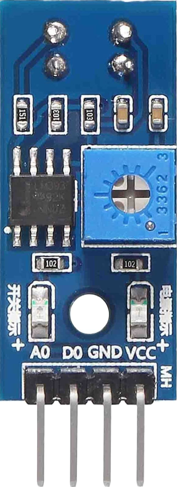
The TCRT5000 is an infrared (IR) sensor module that integrates an IR emitter and a phototransistor in a single package. It is designed for detecting objects and measuring proximity by emitting infrared light and sensing the reflected light from nearby objects. The sensor is highly sensitive to reflective surfaces and is commonly used in robotics, line-following robots, optical encoders, and other automation systems.
Explore Projects Built with TCRT5000

Explore Projects Built with TCRT5000
Common Applications
- Line-following robots
- Object detection in robotics
- Proximity sensing
- Optical encoders for motor speed and position control
- Edge detection in conveyor systems
Technical Specifications
The TCRT5000 sensor has the following key technical specifications:
| Parameter | Value |
|---|---|
| Operating Voltage | 3.3V to 5V |
| Forward Current (IR LED) | 60 mA (max) |
| Collector Current | 1 mA (typical) |
| Peak Wavelength (IR LED) | 950 nm |
| Detection Range | 2 mm to 15 mm (optimal: 2-10 mm) |
| Operating Temperature | -25°C to +85°C |
| Dimensions | 10.2 mm x 5.8 mm x 7 mm |
Pin Configuration and Descriptions
The TCRT5000 has four pins, as described in the table below:
| Pin Number | Name | Description |
|---|---|---|
| 1 | Emitter (A) | Anode of the IR LED. Connect to a current-limiting resistor and then to VCC. |
| 2 | Emitter (K) | Cathode of the IR LED. Connect to ground. |
| 3 | Collector (C) | Collector of the phototransistor. Connect to a pull-up resistor and then to VCC. |
| 4 | Emitter (E) | Emitter of the phototransistor. Connect to ground. |
Usage Instructions
How to Use the TCRT5000 in a Circuit
- Power Supply: Connect the IR LED anode (Pin 1) to a current-limiting resistor (typically 220Ω to 330Ω) and then to the power supply (3.3V or 5V). Connect the cathode (Pin 2) to ground.
- Phototransistor Connection: Connect the phototransistor collector (Pin 3) to a pull-up resistor (e.g., 10kΩ) and then to the power supply. Connect the emitter (Pin 4) to ground.
- Output Signal: The voltage at the phototransistor collector will vary depending on the amount of reflected IR light. When an object is detected, the reflected light increases, causing the phototransistor to conduct more current and lowering the output voltage.
Important Considerations
- Distance Sensitivity: The TCRT5000 is most effective at detecting objects within 2-10 mm. Beyond this range, the sensitivity decreases significantly.
- Surface Reflectivity: The sensor works best with reflective surfaces. Matte or dark surfaces may reduce detection accuracy.
- Ambient Light: Minimize ambient light interference by shielding the sensor or using it in controlled lighting conditions.
- Resistor Selection: Use appropriate resistors for the IR LED and phototransistor to ensure proper operation and avoid damage.
Example: Connecting TCRT5000 to Arduino UNO
Below is an example of how to connect the TCRT5000 to an Arduino UNO for object detection:
Circuit Connections
- IR LED Anode (Pin 1): Connect to a 220Ω resistor, then to Arduino 5V.
- IR LED Cathode (Pin 2): Connect to Arduino GND.
- Phototransistor Collector (Pin 3): Connect to a 10kΩ pull-up resistor, then to Arduino 5V. Also, connect this pin to an Arduino digital input pin (e.g., D2).
- Phototransistor Emitter (Pin 4): Connect to Arduino GND.
Arduino Code
// TCRT5000 Object Detection Example
// Connect the phototransistor output to Arduino digital pin 2

const int sensorPin = 2; // Pin connected to the phototransistor output
const int ledPin = 13;   // Built-in LED for visual feedback

void setup() {
  pinMode(sensorPin, INPUT); // Set sensor pin as input
  pinMode(ledPin, OUTPUT);   // Set LED pin as output
  Serial.begin(9600);        // Initialize serial communication
}

void loop() {
  int sensorValue = digitalRead(sensorPin); // Read sensor output

  if (sensorValue == LOW) {
    // Object detected (IR light reflected)
    digitalWrite(ledPin, HIGH); // Turn on LED
    Serial.println("Object detected!");
  } else {
    // No object detected
    digitalWrite(ledPin, LOW); // Turn off LED
    Serial.println("No object detected.");
  }

  delay(100); // Small delay for stability
}
Troubleshooting and FAQs
Common Issues and Solutions
No Detection or False Readings:
- Cause: Incorrect resistor values or poor connections.
- Solution: Verify the resistor values (220Ω for IR LED, 10kΩ for pull-up) and check all connections.
Inconsistent Output:
- Cause: Ambient light interference or improper alignment.
- Solution: Shield the sensor from ambient light and ensure proper alignment with the object.
Short Detection Range:
- Cause: Low surface reflectivity or incorrect positioning.
- Solution: Use reflective surfaces and position the object within the optimal range (2-10 mm).
Overheating:
- Cause: Excessive current through the IR LED.
- Solution: Use a current-limiting resistor (220Ω to 330Ω) to protect the IR LED.
FAQs
Q1: Can the TCRT5000 detect transparent objects?
A1: The TCRT5000 is not effective at detecting transparent objects, as they do not reflect sufficient IR light.
Q2: How can I increase the detection range?
A2: The detection range is limited by design. However, using highly reflective surfaces and ensuring proper alignment can improve performance.
Q3: Can I use the TCRT5000 with a 3.3V system?
A3: Yes, the TCRT5000 is compatible with 3.3V systems, but ensure the resistors are appropriately selected for the lower voltage.
Q4: What is the typical response time of the TCRT5000?
A4: The TCRT5000 has a fast response time, typically in the microsecond range, making it suitable for high-speed applications.